Search for what you are looking for
Distribution electrical appliances
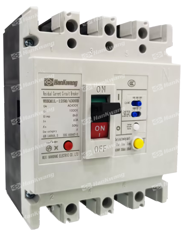
WHKM1L RCCB
The WHKM1L series of residual current circuit-breakers (hereinafter referred to as the "circuit breakers") is one of the new types of circuit breakers developed by our company using advanced international design and manufacturing technologies.
Product Details
Model and Meaning
Technical Specifications
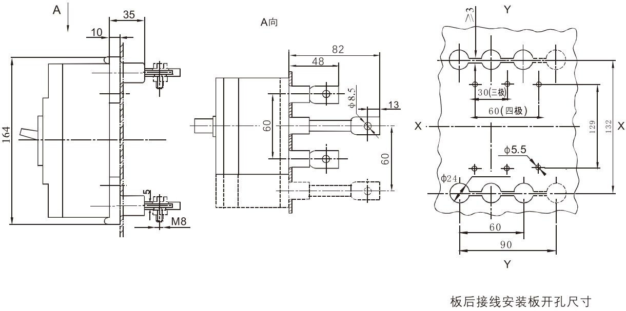
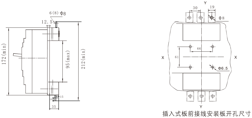
Appearance and dimensions
Other
WHKM1L series residual current circuit-breakers (hereinafter referred to as circuit breaker) is one of the new circuit breakers developed and developed by our company using international advanced design and manufacturing technology. Its rated insulation voltage is 1000V, which is suitable for infrequent conversion and infrequent motor starting in circuits with AC 50Hz, rated working voltage 400V and below, and rated working current to 630A.
Circuit breakers have overload, short circuit and undervoltage protection functions, which can protect lines and power equipment from damage. At the same time, they can also provide protection against fire hazards caused by long-standing ground faults that cannot be detected by overcurrent protection.
Circuit breakers are divided into two categories: M type (higher breaking type) and H type (high breaking type) according to their rated limit short-circuit breaking capacity (Icu). The circuit breaker has the characteristics of small size, high breaking, short flying arc and anti-vibration. The circuit breaker can be installed vertically (i.e. vertically) or horizontally (i.e. transversely)
This circuit breaker cannot be reversed, that is, only 1, 3 and 5 are allowed to be connected to the power line, and 2, 4 and 6 are allowed to be connected to the load line.
Circuit breakers are suitable for isolation.
| WHK | M | 1 | L | — | ☐ | ☐ | ☐ | / | ☐ | ☐ | ☐ | ☐ | ☐ |
|---|---|---|---|---|---|---|---|---|---|---|---|---|---|
|
enterprise Code |
plastic Enclosure Style break Road instrument |
Design Serial number |
With leftover Residual electricity Stream protection |
Shell frame etc. Class rating current |
Rated limit Short circuit break Competency Level |
operation Way (4 |
Number of poles |
Tripping side Formula and attachments Part Code |
Purpose Code (3 |
Quadrupole production Product code (2 |
Leakage telegram Police unit Module (1 |
Note: 1) The module without leakage alarm unit has no code; The module with leakage alarm unit is represented by I in the first working mode and II in the second working mode.
2) Three-pole products have no code names, and four-pole products are classified as A, B, C, and D.
3) The circuit breaker for power distribution has no code, and the new circuit breaker for protecting the motor is represented by 2.
4) There is no code for direct operation of the handle: electric operation is represented by P; Turning the handle operation is indicated by Z.
◆Technical Performance Indicators (Table 3)
※ Note: 1. The limit breaking and arc distance includes horizontal and vertical installation;
2. When this series of three-pole circuit breakers is connected to a three-phase load, the load cannot have a neutral wire, otherwise the circuit breaker will malfunction;
3. When this series of three-pole circuit breakers is connected to a single-phase load, the phase wire is connected to the left pole, the neutral wire is connected to the right pole, and do not connect to the center pole.
Residual current protection action schedule four
| Model | WHKM1L-125 | WHKM1L-250 | WHKM1L-400 | WHKM1L-630 | |||||||||
|---|---|---|---|---|---|---|---|---|---|---|---|---|---|
|
Frame current Im (A) |
125 | 250 | 400 | 630 | |||||||||
|
Rated current In(A) |
16.20.25.32, 40.50.63、80、100.125 |
100、125、140、160、 180、200、225、250 |
225、250、315 350、400 |
400、500、630 | |||||||||
| Infinity | 3/4 | ||||||||||||
|
Rated insulation voltage Ui(V) |
AC1000 | ||||||||||||
|
Rated operating voltage Ue(V) |
AC400 | ||||||||||||
|
Rated impulse withstand voltage Uimp(V) |
8000 | 12000 | |||||||||||
|
Arc discharge distance (mm) |
>50 | ×100 | |||||||||||
| Breakdown capability level | M | H | M | H | M | H | M | H | |||||
|
Limit short-circuit breaking capacity lcu(kA) |
AC400V | 35 | 75 | 35 | 75 | 65 | 85 | 65 | 85 | ||||
|
Operating short-circuit breaking capacity lcs(kA) |
AC400V | 18 | 50 | 18 | 50 | 42 | 65 | 42 | 65 | ||||
|
Rated residual operating current I△n(mA) |
Non-delay type | 100/300/500 | 300V500/1000 | ||||||||||
| Delayed type | 100/300/500 | 300V500/1000 | |||||||||||
|
Rated residual operating current I△no(mA) |

|
||||||||||||
|
Rated residual short-circuit closing (opening) capacity I△m(kA) |

|
||||||||||||
| Operational performance (times) | Power on | 7000 | 7000 | 7000 | 7000 | ||||||||
| No electricity | 10000 | 10000 | 10000 | 10000 | |||||||||
|
Dimensions of the shape (mm) |
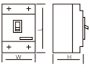
|
W | 92 | 122 | 107 | 142 | 150 | 198 | 210 | 280 | |||
| L | 150 | 150 | 165 | 165 | 257 | 257 | 280 | 280 | |||||
| H | 92 | 92 | 90 | 90 | 106.5 | 106.5 | 115.5 | 115.5 | |||||
| Shunt release | ○ | ○ | ○ | ○ | ○ | ○ | ○ | ○ | |||||
| Undervoltage release | ○ | ○ | ○ | ○ | ○ | ○ | ○ | ○ | |||||
| Leakage alarm unit module | ○ | ○ | ○ | ○ | ○ | ○ | ○ | ○ | |||||
| Auxiliary contact | ○ | ○ | ○ | ○ | ○ | ○ | ○ | ○ | |||||
| Alarm contact | ○ | ○ | ○ | ○ | ○ | ○ | ○ | ○ | |||||
| Electric operating mechanism | ○ | ○ | ○ | ○ | ○ | ○ | ○ | ○ | |||||
| Rotary handle operating mechanism | ○ | ○ | ○ | ○ | ○ | ○ | ○ | ○ | |||||
2. When this series of three-pole circuit breakers is connected to a three-phase load, the load cannot have a neutral wire, otherwise the circuit breaker will malfunction;
3. When this series of three-pole circuit breakers is connected to a single-phase load, the phase wire is connected to the left pole, the neutral wire is connected to the right pole, and do not connect to the center pole.
Residual current protection action schedule four
| Residual current | I △ n | 2I △ n | 5I △ n | 10I △ n | |
|---|---|---|---|---|---|
| Non-delay type | Max OFF Time (s) | 0.2 | 0.1 | 0.04 | 0.04 |
| Delay type | Max OFF Time (s) | 0.5/1.15 | 0.35/1 | 0.25/0.9 | 0.25/0.9 |
| 2I △ limit non-driving time at n △ t (s) | - | 0.1/0.5 | - | - | |
This circuit breaker product meets the following standards:
IEC60947-2 and GB14048.2 Low voltage circuit breakers and Annex B circuit breakers with residual current protection
IEC60947-4 and GB14048.4 Contactors and motor starters
IEC60947-5. 1 and G814048.5 Electromechanical control circuit electrical appliances
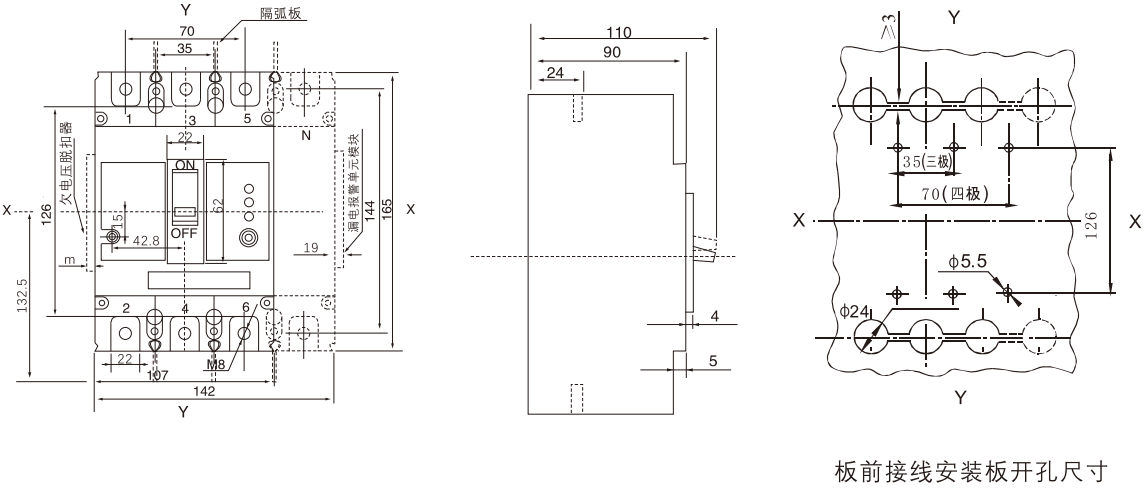
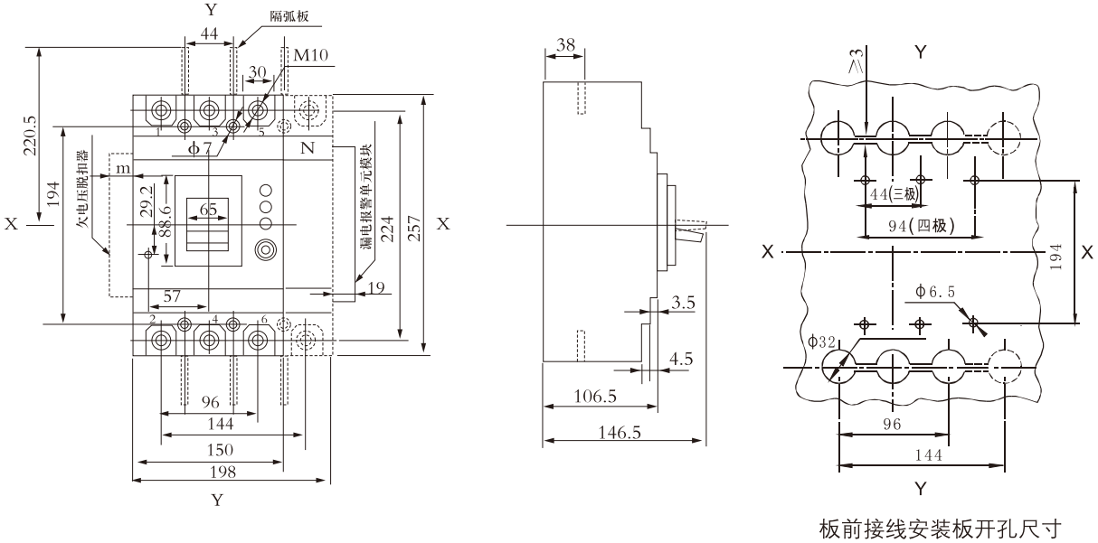
WHKM1L-125 board front wiring (three-pole, four-pole) X-X, Y-Y are three-pole circuit breaker centers
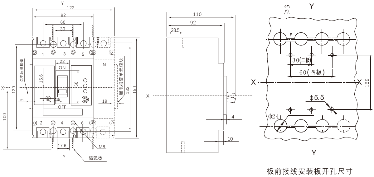
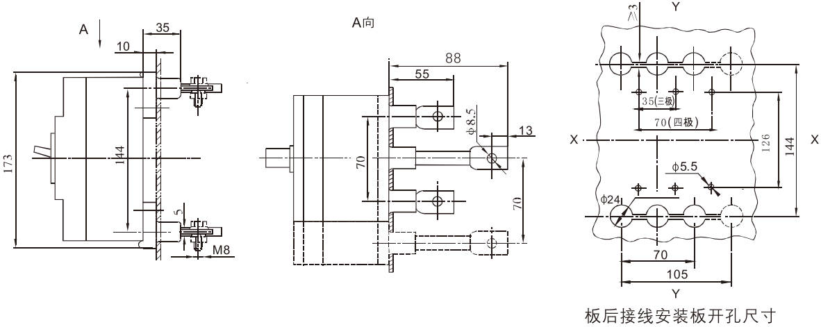
Rear wiring of WHKM1L-125 board (three-pole, four-pole) X-X, Y-Y are the center of three-pole circuit breaker
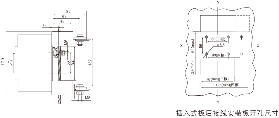
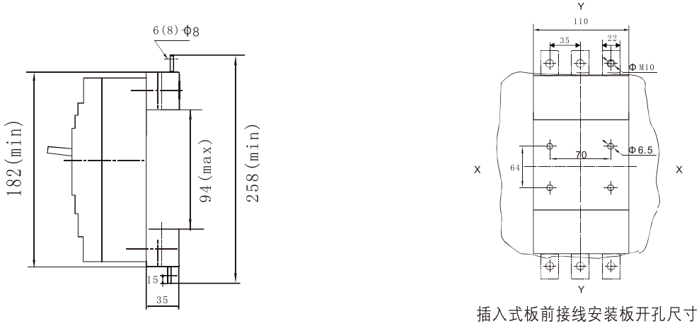
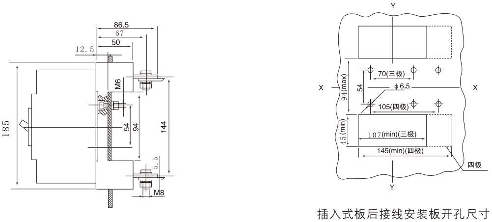
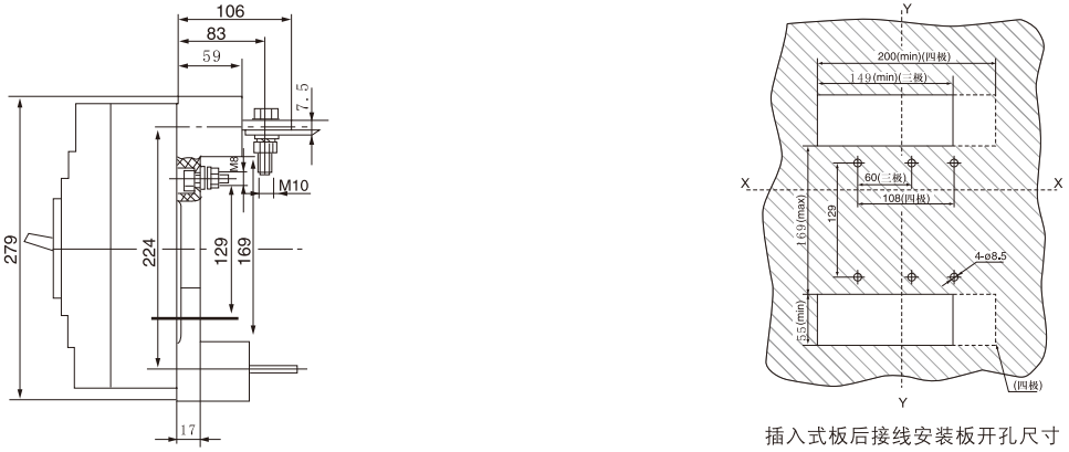
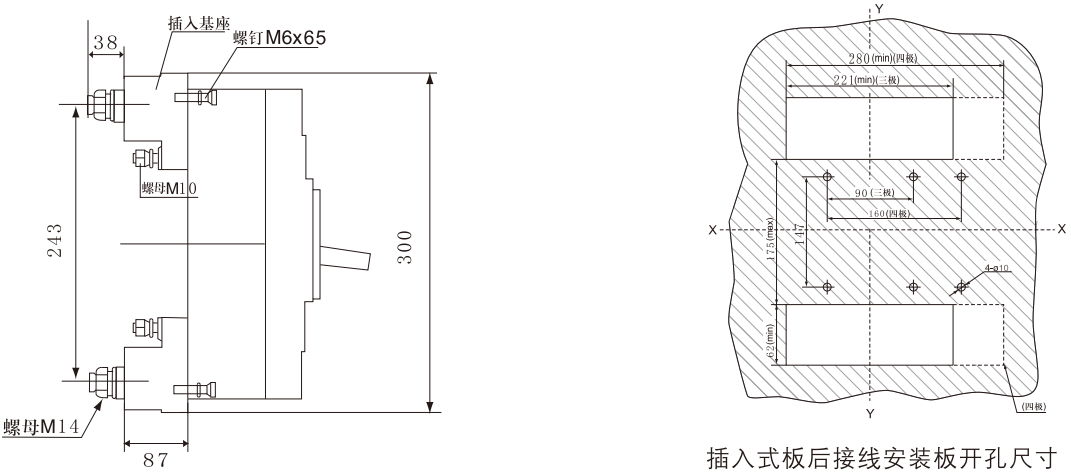
WHKM1L-125 plug-in board front wiring X-X, Y-Y are the center of three-pole circuit breaker
WHKM1L-125 rear wiring of plug-in board (three-pole, four-pole) X-X, Y-Y are the center of three-pole circuit breaker
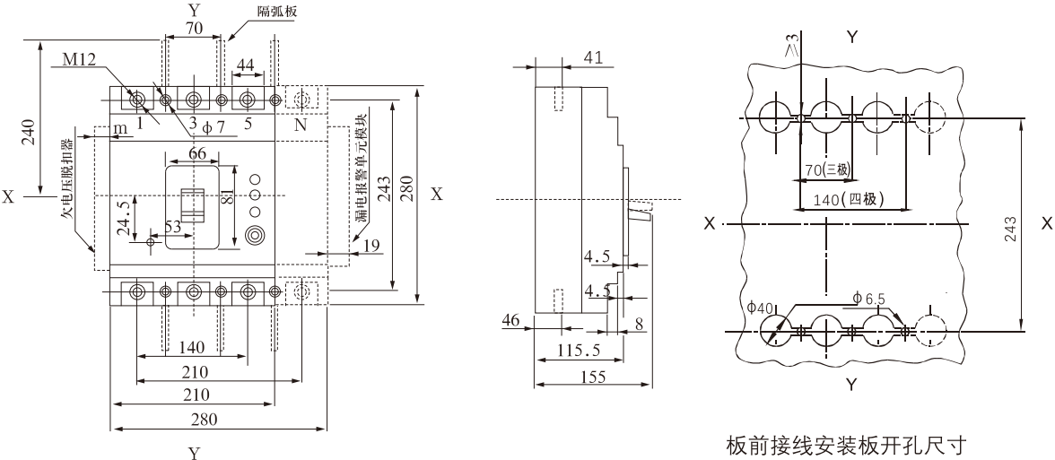
WHKM1L-250 board front wiring (three-pole, four-pole) X-X, Y-Y are three-pole circuit breaker centers
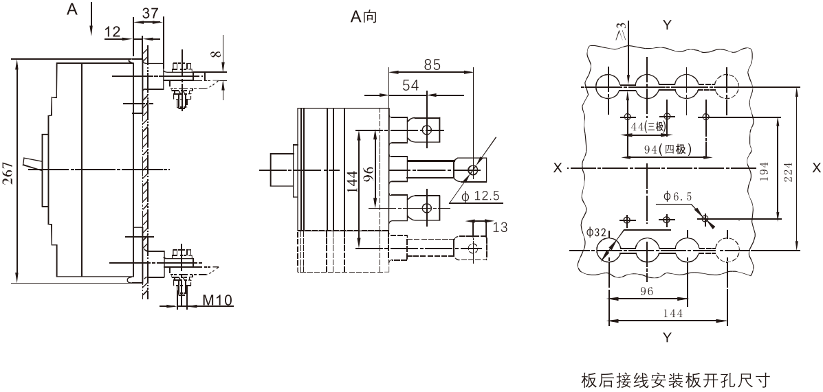
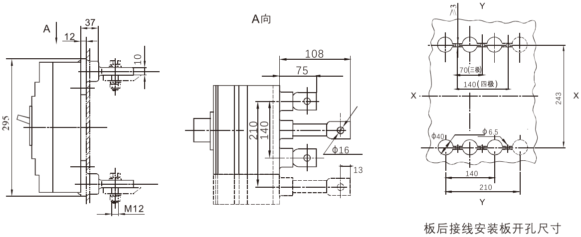
WHKM1L-250 board rear wiring (three-pole, four-pole) X-X, Y-Y are the center of three-pole circuit breaker
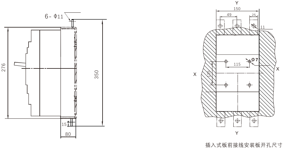
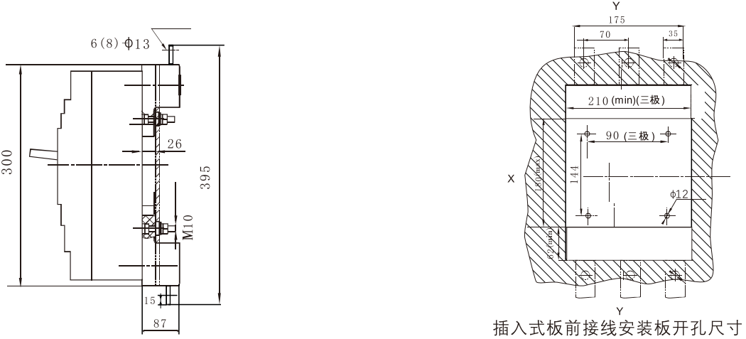
WHKM1L-250 plug-in board front wiring X-X, Y-Y are the center of three-pole circuit breaker
WHKM1L-250 rear wiring of plug-in board (three-pole, four-pole) X-X, Y-Y are the center of three-pole circuit breaker
WHKM1L-400 board front wiring (three-pole, four-pole) X-X, Y-Y are three-pole circuit breaker centers
WHKM1L-400 board rear wiring (three-pole, four-pole) X-X, Y-Y are the center of three-pole circuit breaker
WHKM1L-400 plug-in board front wiring X-X, Y-Y are the center of three-pole circuit breaker
WHKM1L-400 plug-in board rear wiring (three-pole, four-pole) X-X, Y-Y are the center of three-pole circuit breaker
WHKM1L-630 board front wiring (three-pole, four-pole) X-X, Y-Y are three-pole circuit breaker centers
WHKM1L-630 board rear wiring (three-pole, four-pole) X-X, Y-Y are the center of three-pole circuit breaker
WHKM1L-630 plug-in board front wiring X-X, Y-Y are the center of three-pole circuit breaker
WHKM1L-630 Plug-in board rear wiring (three-pole, four-pole) X-X, Y-Y are the center of three-pole circuit breaker
Internal and External Accessories
◆ Internal accessories for circuit breakers
According to the user's needs, the circuit breaker accessories can be directly led out, or a terminal block can be installed.
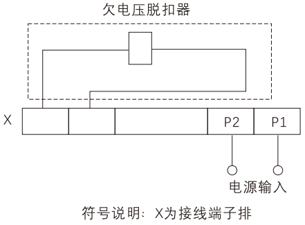
Undervoltage release
Under voltage release: AC50 Hz230V or 400V.
Wiring diagram of external undervoltage module (the wiring diagram of internal accessories of circuit breaker is in the virtual frame)
※ Undervoltage module thickness: 20mm
Undervoltage release power
| Distribution circuit breaker | Undervoltage Release Power (VA) | |
|---|---|---|
| AC230V | AC400V | |
| WHKM1L-125 | 2.6 | 3.3 |
| WHKM1L-250 | 3.8 | 3.3 |
| WHKM1L-400 | 3.7 | 2.7 |
| WHKM1L-630 | 2.5 | 2.8 |
When the rated working voltage is 35% ~ 70%, the undervoltage release device should reliably trip the circuit breaker;
When the rated working voltage is 85% ~ 110%, the undervoltage release shall ensure that the circuit breaker is closed;
When the rated operating voltage is less than 35%, the undervoltage release shall prevent the circuit breaker from closing.
Warning: The undervoltage release must be energized before the circuit breaker can be closed and closed again. Otherwise, the circuit breaker will be damaged!
◆ Shunt release
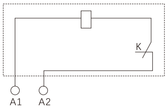
Wiring diagram (the wiring diagram of internal accessories of circuit breaker is in the dummy box)
K: The micro switch connected in series with the coil inside the shunt release device is a normally closed contact. When the circuit breaker is opened, the contact opens itself and closes when it is closed.
Voltage specifications: AC50 Hz230V or 400V; DC220V
Between 70 and 110% of the rated control power supply voltage, the shunt release shall reliably trip the circuit breaker.
※ (Shunt release long wire type wire length: 50 mm)
(Shunt Release Terminal Type Thickness: 20 mm)
◆ Leakage alarm unit module
There are two ways of leakage alarm unit module. Users can explain when ordering according to their needs:
Mode 1 (represented by Ⅰ): When leakage occurs, the leakage alarm module sends out a signal and the circuit breaker trips;
Mode 2 (represented by Ⅱ): When leakage occurs, the leakage alarm module sends out a signal, but the circuit breaker does not trip.
Note: The second method is to meet the needs of special occasions. Please consider carefully when using this function to protect electrical appliances.
Wiring diagram (the wiring diagram of internal accessories of leakage alarm module is in the virtual box)
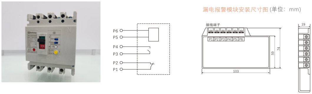
Specifications: P5-P6 terminal input power supply is AC50Hz230V or 400V.
P1-P2, P3-P4 angle contact capacity is AC230V5A.
Alarm contact
| Circuit breaker is in "on" and "closed" position |
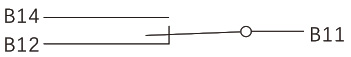
|
| Position when the circuit breaker is "free trip" (alarm) |
B11, B14 transition from OFF state to ON state B11, B12 transition from the ON state to the OFF state |
* (Shunt release long wire type wire length: 50 mm) (Shunt release terminal type thickness: 20 mm)
Auxiliary contact
| When the circuit breaker is in the "off" position |
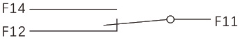
|
| When the circuit breaker is in the "closed" position |
F11, F12 transition from ON state to OFF state F11, F14 transition from OFF state to ON state |
※ (Shunt release long wire type wire length: 50 mm) (Shunt release terminal type thickness: 20 mm)
Rated current of auxiliary contact and alarm contact
| Classification |
Current rating of shell grade Inm (A) |
Agreed heating current Ith (A) |
Rating at AC400V Operating current Ie (A) |
Rating at DC220V Operating current le (A) |
|---|---|---|---|---|
| Auxiliary contact | ≤225 | 3 | 0.3 | 0.15 |
| ≥400 | 3 | 0.4 | 0.2 | |
| Alarm contact | 16 ≤ Inm ≤ 800 | AC220V/1A | 0.15 |
Power-on operation performance of auxiliary contacts and corresponding test conditions
| Use categories | connect | Break up |
Power-on operation No. of cycles |
Operations per minute No. of cycles |
Power-on time | ||||
|---|---|---|---|---|---|---|---|---|---|
| I/le | U/Ue |
Cos φ or T0.95 |
I/le | U/Ue |
cosp or T0.95 |
||||
| AC-15 | 10 | 1 | 0.3 | 1 | 1 | 0.3 | 6050 | 6 | ≥ 0. 05 s |
| DC-13 | 1 | 1 | 6Pe | 1 | 1 | 6Pe | ≥ T 0. 95 | ||
On and off capability of auxiliary contact under abnormal condition
| Use categories | connect | Break up |
Power-on operation No. of cycles |
Operations per minute Number of cycles |
Power-on time | ||||
|---|---|---|---|---|---|---|---|---|---|
| I/le | U/Ue |
Cos φ or T0.95 |
I/le | U/Ue |
Cos φ or T0.95 |
||||
| AC-15 | 10 | 1.1 | 0.3 | 10 | 1.1 | 0.3 | 10 | 2 | ≥ 0. 05 s |
| DC-13 | 1.1 | 1.1 | 6Pe | 1.1 | 1.1 | 6Pe | ≥ T 0. 95 | ||
Note: Table 1 above 2. T0.95 = 6Pe is an empirical formula, where Pe is in "watts" and T0.95 is in milliseconds.
2. When the total number of operating performances of the circuit breaker is less than 6050, the number of energized operating performances of the auxiliary contact may be equal to the total number of operating performances of the circuit breaker.
3. The operating frequency and energization time are allowed to be consistent with those of the main circuit of the circuit breaker.
◆ External accessories for circuit breakers
CD2L electric operating mechanism
Wiring diagram of electric operating mechanism (the internal wiring diagram of electric motor operating mechanism is in the virtual box)
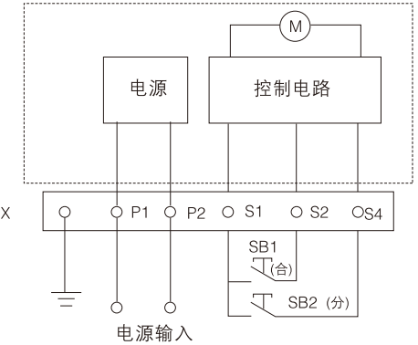
Voltage specification: AC50Hz110V, 230V
DC110V, 220V
Symbol description:
SB1, SB2 operation buttons (user's own)
X Terminal Block
P1 and P2 are external power input
Starting Current, Power and Life of Electric Operating Mechanism
| Equipped circuit breaker | Starting Current (A) | Starting Power (VA) | Life (times) |
|---|---|---|---|
| WHKM1L-125 | ≤0.5 | 12 | 10000 |
| WHKM1L-250 | ≤0.5 | 12 | 8000 |
| WHKM1L-400 | ≤2 | 35 | 5000 |
| WHKM1L-630 | ≤2 | 35 | 5000 |
Note: After the circuit breaker is tripped, the electric operating mechanism must first buckle the circuit breaker before closing.
◆ Height of electric operating mechanism
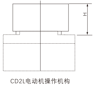
| Electric operating mechanism | Circuit breaker model | H (mm) |
|---|---|---|
| CD2L-125 | WHKM1L-125 | 89.5 |
| CD2L-250 | WHKM1L-250 | 93 |
| CD2L-400 | WHKM1L-400 | 142 |
| CD2L-630 | WHKM1L-630 | 146 |
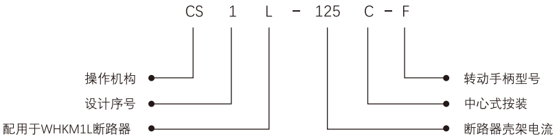
CS1L rotary handle operation mechanism (universal for three-pole and four-pole circuit breakers)
⊙ Model meaning
◆ Features:
The operating mechanism adopts unique design and transmission structure, and realizes the closing, opening and re-buckle of the molded case circuit breaker by rotating the handle. Flexible operation, smooth operation, small operation force, easy installation, the overall performance and quality of the mechanism are superior to other similar products.
◆ Purpose:
This mechanism is specially used for WHKM1L series molded case circuit breaker. It can realize the operation requirements of chest of drawers, distribution cabinet, power box, etc. on the panel by rotating the handle, and ensure that the cabinet door panel cannot be opened (i.e. interlocked with the door) when the circuit breaker is closed.
Outline and dimensions: (unit: mm)
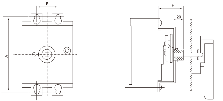
| Model of manual mechanism | Circuit breaker model | A | B | H |
|---|---|---|---|---|
| CS1L-125/C | WHKM1L-125 | 104 | 30 | 49 |
| CS1L-250/C | WHKM1L-250 | 143 | 35 | 55 |
| CS1L-400/C | WHKM1L-400 | 194 | 138 | 74 |
| CS1L-630/C | WHKM1L-630 | 87.5 | 198 | 66 |
The CS1 handle mechanism can be equipped with two kinds of operating handles: one is "F" square handle and the other is "A" round handle. The opening size of the door panel is shown in the following figure.
◆ Operating handle features:
1. When the circuit breaker is in the closed state, the cabinet door cannot be opened:
2. If the operating handle or manual mechanism is faulty in the closed state, the cabinet door can be opened by operating the emergency unlocking device on the operating handle;
3. Corresponding to different specifications of manual mechanisms, the matching manual handles have the same door panel openings.
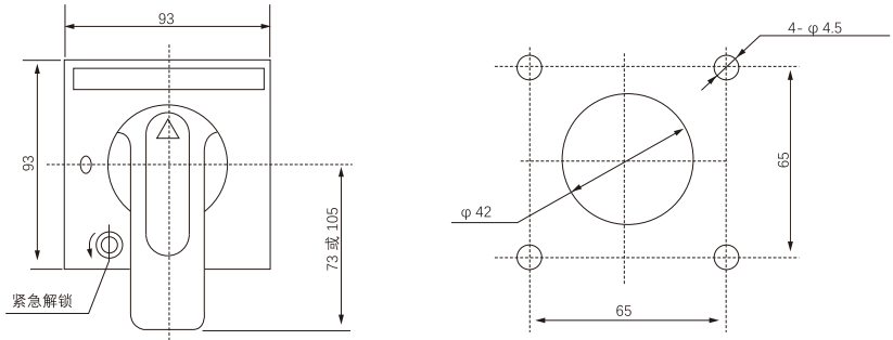
The shape of "F" square handle and the size of the opening of the door panel (the distance between the opening center and the hinge is not less than 100mm)
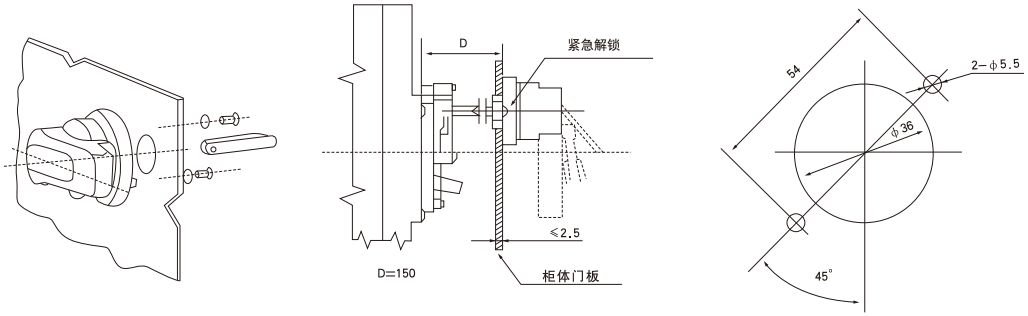
"A" type circular handle shape and door panel opening size (the distance between the opening center and the hinge is not less than 100mm)
Notes: 1. The length of the square shaft is D = 150. When the length is greater than 150mm, it should be indicated when ordering;
2. The manual operation mechanism is equipped with an "F" handle, and model CS1L can be filled with "F", such as CS1L-100C-F: it is equipped with an "A" handle, model CS1L can be filled with "A", such as CS1L-100C-A.
Warning users: Manual operation mechanism must order with our company to ensure product quality. If the user purchases it by himself, the company will not be responsible for all adverse consequences after installation and assembly.