Search for what you are looking for
Distribution electrical appliances
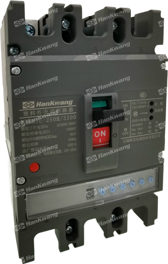
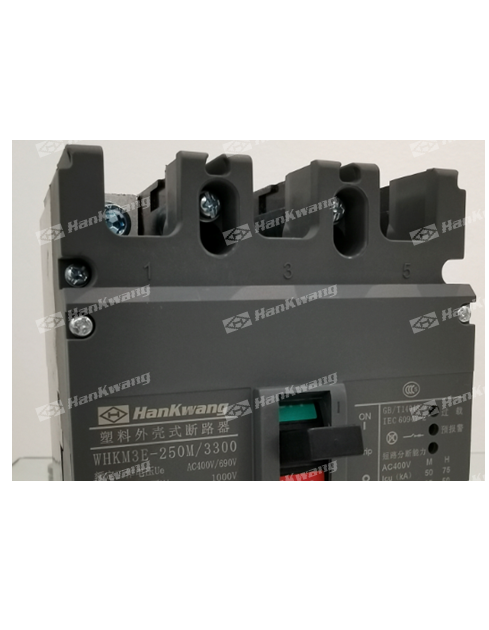
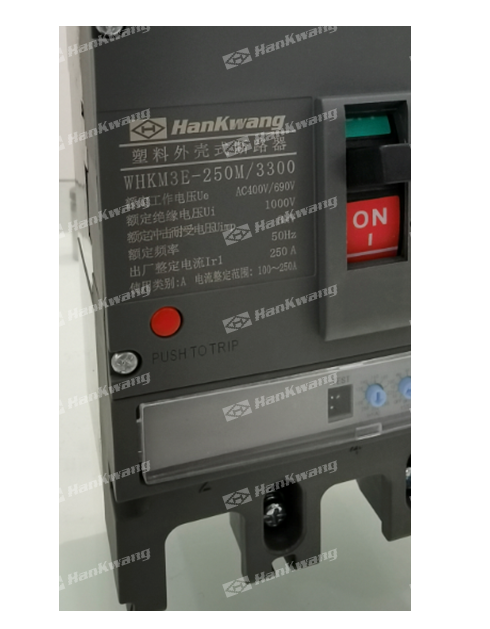
WHKM3E MCCB
The WHKM3E series electronic molded case circuit breaker (hereinafter referred to as the circuit breaker) is a new type of circuit breaker developed by our company using advd design and manufacturing technologies. With a rated insulation voltage of 1000V, it is suitable for circuits with an AC frequency of 50Hz, a rated operatinoltage up to 690V, and a rated current up to 800A, for use in infrequent switching and motor protection.
Product Details
Model and Meaning
Technical Specifications
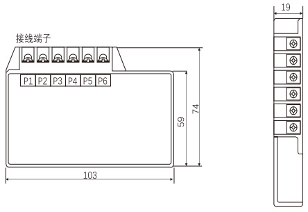
Appearance and dimensions
Other
The WHKM3E series electronic molded case circuit breaker (hereinafter referred to as the circuit breaker) is one of the new types of circuit breakers deve our company using advanced design and manufacturing technologies. With a rated insulation voltage of 1000V, it is suitable for circuits with AC 50Hz, rated operatinoltage up to 690V, and rated current up to 800A, for infrequent switching and motor protection. The circuit breaker features overload long-time inversedelay, short-circuit short-time inverse time delay, short-circuit short-time definite time delay, short-circuit instantaneous, and undervoltage protection functions, which protect circuits and power suppuipment from damage, and can provide circuit breakers suitable for low temperatures down to -40°C.
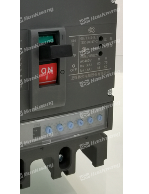
Classified by rated ultimate short-circuit breaking capacity (Icu), the circuit breaker is ded into two types: Type M (high breaking type) and Type H (high breaking type). This circuit breaker features a compact size, high breaking capacity, short arc distance, and vibratio resistance.
The circuit breaker can be installed vertically (i.e. vertically) or horizontally (i.e. horizontally).
The circuit breaker cannot be reversed, that is, only 1, 3, and 5 can be connected to the power line, and 2, 4, and 6 can be connected to the load line.
Circuit breakers are suitable for isolation.
| WHK | M | 3 | E | — | ☐ | ☐ | ☐ | / | ☐ | ☐ | ☐ | ☐ |
|---|---|---|---|---|---|---|---|---|---|---|---|---|
|
enterprise Code |
Plastic outer Shell fracture Road instrument |
Design Serial number |
Electronic type |
Shell frame etc. Class rating current |
Rated limit Short circuit break Competency Level |
Operator Formula (2 |
Number of poles |
Tripping mode And accessories No. (see Table II) |
Purpose Code (1 |
Humid tropics Type TH |
◆ The type of neutral electrode (N-pole) of four-pole products is: N-pole overcurrent protection current and time parameters automatically track the phase line setting value 100%, and N-pole is combined and split together with the other three poles (N-pole is closed first and then split);
◆ According to the rated current: WHKM3E-125 has 32, 63, 125 AWHKM3E-250 has 250A; 400A for WHKM3E-400; WHKM3E-630 is 630A; WHKM3E-800 is 800A;
◆ The wiring methods are divided into five types: front-board wiring, back-board wiring, plug-in front-board wiring, plug-in back-board wiring, and pull-out wiring;
◆ According to whether the circuit breaker has accessories or not, it is divided into two types: with accessories and without accessories. Accessories are divided into internal accessories and external accessories: internal accessories include shunt release, undervoltage release, auxiliary contact and alarm contact; External accessories include manual operation mechanism, motor operation mechanism, handheld WHKM3E special tester, FWB1 temperature alarm module
| Model | WHKM3E-125 | WHKM3E-250 | WHKM3E-400 | |||||||
|---|---|---|---|---|---|---|---|---|---|---|
|
Rated current of the enclosure rating lnm(A) |
125 | 250 | 400 | |||||||
|
Rated current In(A) |
32 | 63 | 125 | 250 | 400 | |||||
|
Overload long-delay setting current Ir1(A) |
16,20 25,32 |
32,36,40 45,50,55 60,63 |
63,65,70, 75,80,85. 90,95,125 |
100,125,140,150, 160,180,200,225, 250 |
160,200,225,250, 280,315,350,400 |
|||||
| Rated operating voltage Ue (V) | 400,690 | |||||||||
| Rated insulation voltage Ui (V) | 1000 | |||||||||
| Rated impulse withstand voltage (V) | 8000 | 12000 | ||||||||
| Infinity | 3/4 | |||||||||
| Breakdown capability level | M | H | M | H | M | H | ||||
|
Rated short-circuit breaking capacity Ics (kA) |
AC400V | 50 | 75 | 50 | 75 | 65 | 85 | |||
| AC690V | 20 | |||||||||
|
Rated short-circuit breaking capacity for operation lcs(kA) |
AC400V | 35 | 50 | 35 | 50 | 42 | 65 | |||
| AC690V | 10 | |||||||||
|
Rated short-circuit withstand current lcw(kA)/1s |
5 | |||||||||
| Usage Categories | A | B | ||||||||
| Arc discharge distance(mm) | ≯50(0)** | ≯100(0)** | ||||||||
| Electrical lifespan (number of cycles) | 7000 | 7000 | ||||||||
| Mechanical lifespan | Maintenance-free | 10000 | 10000 | |||||||
| Maintenance is required. | 20000 | 20000 | ||||||||
| Dimensions of the shape |

|
W | 92 | 122 | 107 | 142 | 150 | 198 | ||
| L | 150 | 165 | 257 | |||||||
| H | 92 | 90 | 106.5 | |||||||
| Front panel wiring | ○ | ○ | ○ | |||||||
| Backboard wiring | ○ | ○ | ○ | |||||||
| Plug-in wiring | ○ | ○ | ○ | |||||||
| Extractive wiring | ○ | ○ | ○ | |||||||
| Under-voltage trip device | ○ | ○ | ○ | |||||||
| Spring-operated trip device | ○ | ○ | ○ | |||||||
| Auxiliary contact | ○ | ○ | ○ | |||||||
| Alarm contact | ○ | ○ | ○ | |||||||
| Electric motor operating mechanism | ○ | ○ | ○ | |||||||
| Manual operating mechanism | ○ | ○ | ○ | |||||||
| WHKM3E Specialized Tester | ○ | ○ | ○ | |||||||
| Model | WHKM3E-630 | WHKM3E-800 | |||||
|---|---|---|---|---|---|---|---|
|
Rated current of the enclosure rating lnm(A) |
630 | 800 | |||||
|
Rated current In(A) |
630 | 800 | |||||
|
Overload long-delay setting current Ir1(A) |
400,420,440,460,480, 500,530,560,600,630 |
630,640,660,680,700, 720,740,760,780.800 |
|||||
| Rated operating voltage Ue(V) | 400,690 | ||||||
| Rated insulation voltage Ui(V) | 1000 | ||||||
| Rated impulse withstand voltage (V) | 12000 | ||||||
| Infinity | 3/4 | 3/4 | |||||
| Breakdown capability level | M | H | M | H | |||
|
Rated short-circuit breaking capacity Ics (kA) |
AC400V | 65 | 85 | 65 | 85 | ||
| AC690V | 20 | 20 | 20 | 20 | |||
|
Rated short-circuit breaking capacity for operation Ics(kA) |
AC400V | 50 | 65 | 50 | 65 | ||
| AC690V | 15 | 15 | 15 | 15 | |||
|
Rated short-circuit withstand current lom(kAV1s |
10 | 10 | |||||
| Usage Categories | B | B | |||||
| Arc discharge distance(mm) | ≯100 | ≯100 | |||||
| Electrical lifespan (number of cycles) | 7000 | 7000 | |||||
| Mechanical lifespan | Maintenance-free | 10000 | 10000 | ||||
| Maintenance is required. | 20000 | 20000 | |||||
| Dimensions of the shape |

|
W | 210/280 | 210/280 | |||
| L | 280 | 280 | |||||
| H | 115.5 | 115.5 | |||||
| Front panel wiring | ○ | ○ | |||||
| Backboard wiring | ○ | ○ | |||||
| Plug-in wiring | ○ | ○ | |||||
| Extractive wiring | ○ | ○ | |||||
| Under-voltage trip device | ○ | ○ | |||||
| Spring-operated trip device | ○ | ○ | |||||
| Auxiliary contact | ○ | ○ | |||||
| Alarm contact | ○ | ○ | |||||
| Electric motor operating mechanism | ○ | ○ | |||||
| Manual operating mechanism | ○ | ○ | |||||
| WHKM3E Specialized Tester | ○ | ○ | |||||
| *Note: According to GB/T14048.1, the term "life" refers to the probability that an electrical appliance can complete a certain number of operation cycles before requiring repair or replacement of components. | |||||||
The circuit breaker meets the following criteria:
IEC60947-1 and GB140481 General principles for low-voltage switchgear and control equipment
IEC60947-2 and GB140482 Circuit Breakers for Low Voltage Switchgear and Control Equipment and Annex F Additional Tests for Circuit Breakers with Electronic Overcurrent Protection
IEC60947-4-1 and GB1404B.4 Low voltage switchgear and control equipment Electromechanical contactors and motor starters
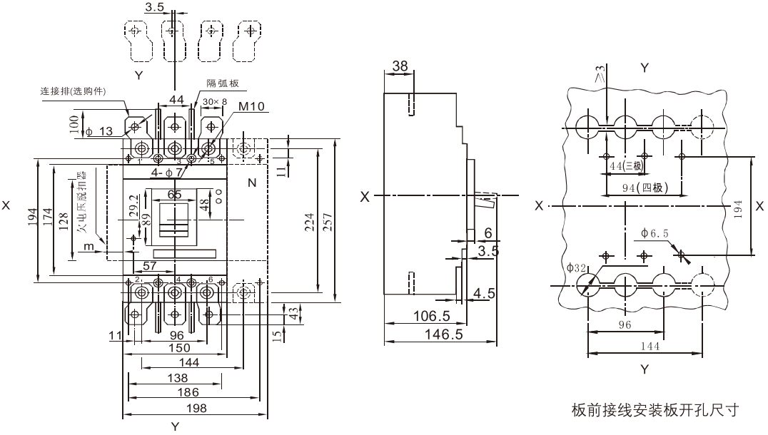
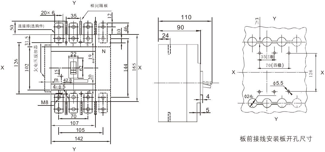
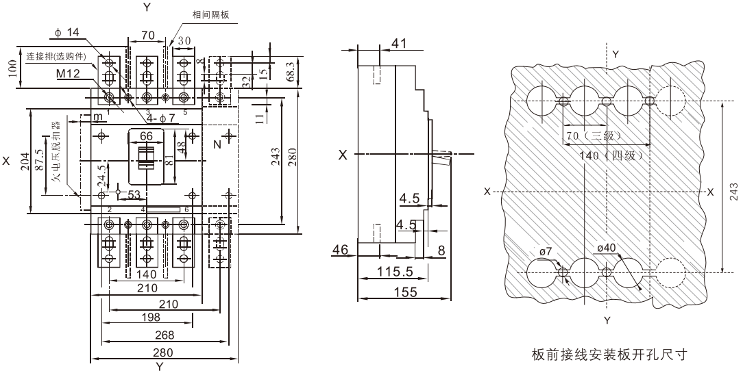
WHKM3E-125 board front wiring (three-pole, four-pole) X-X, Y-Y are three-pole circuit breaker centers
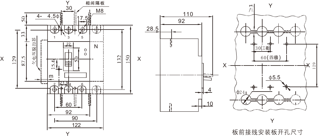
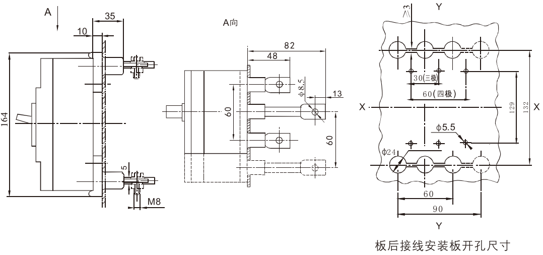
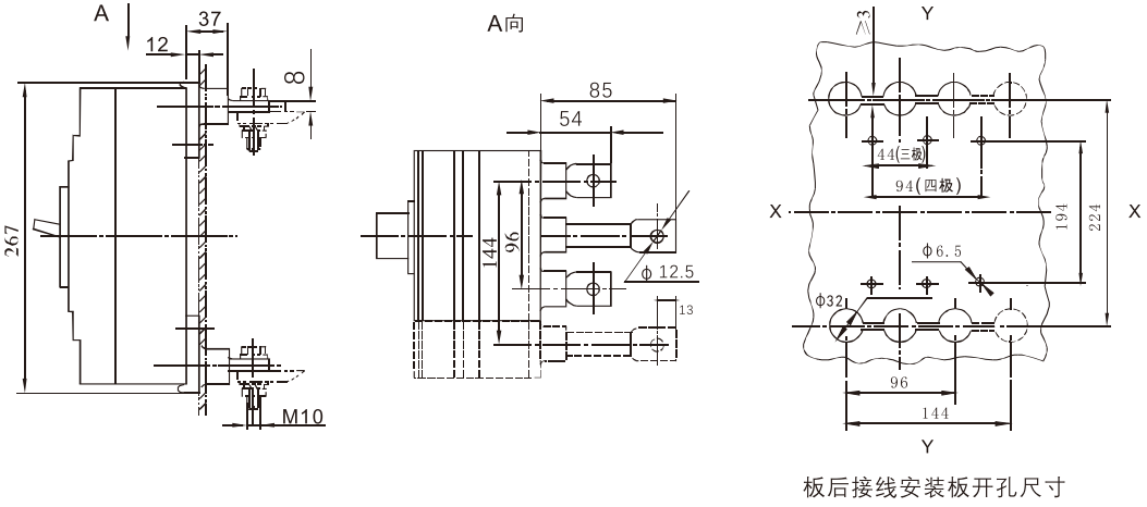
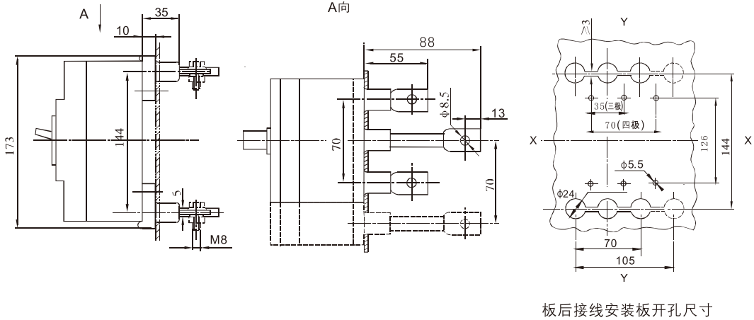
WHKM3E-125 board rear wiring (three-pole, four-pole) X-X, Y-Y are three-pole circuit breaker center
WHKM3E-250 plug-in board front wiring X-X, Y-Y are the center of three-pole circuit breaker
WHKM3E-250 plug-in board rear wiring (three-pole, four-pole) X-X, Y-Y are the center of three-pole circuit breaker
WHKM3E-400 board front wiring (three-pole, four-pole) X-X, Y-Y are three-pole circuit breaker centers
WHKM3E-400 board rear wiring (three-pole, four-pole) X-X, Y-Y are three-pole circuit breaker centers
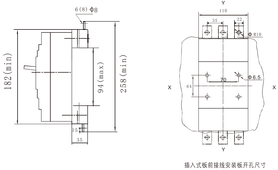
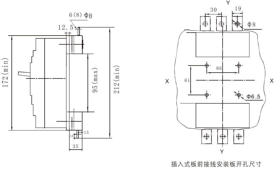
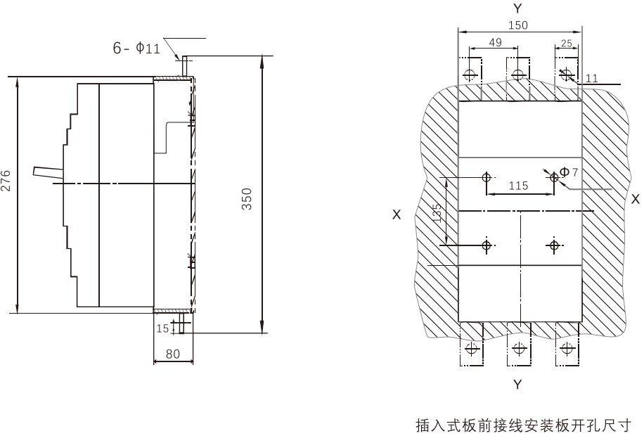
WHKM3E-125 plug-in board front wiring X-X, Y-Y are the center of three-pole circuit breaker
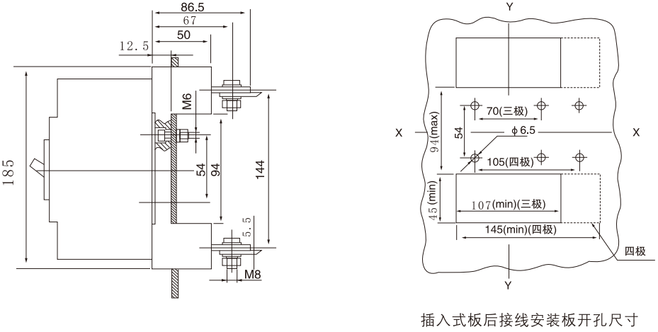
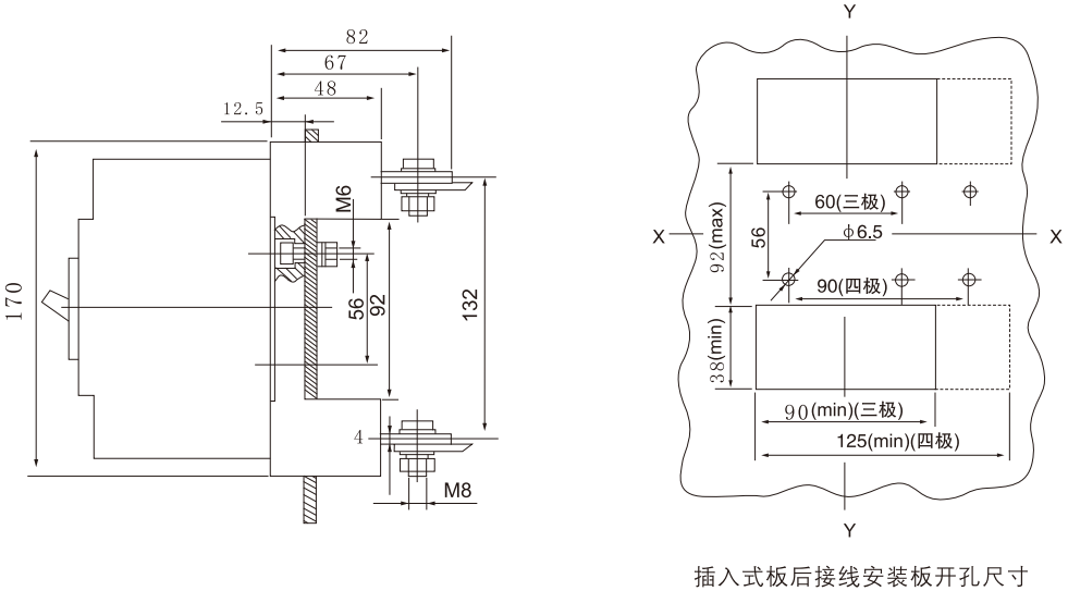
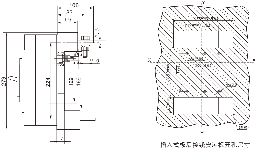
WHKM3E-125 plug-in board rear wiring (three-pole, four-pole) X-X, Y-Y are the center of three-pole circuit breaker
WHKM3E-250 board front wiring (three-pole, four-pole) X-X, Y-Y are three-pole circuit breaker centers
WHKM3E-250 board rear wiring (three-pole, four-pole) X-X, Y-Y are three-pole circuit breaker center
WHKM3E-400 plug-in board front wiring X-X, Y-Y are the center of three-pole circuit breaker
WHKM3E-400 plug-in board rear wiring (three-pole, four-pole) X-X, Y-Y are the center of three-pole circuit breaker
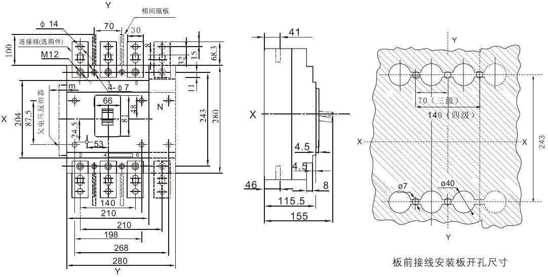
WHKM3E-630 board front wiring (three-pole, four-pole) X-X, Y-Y are three-pole circuit breaker centers
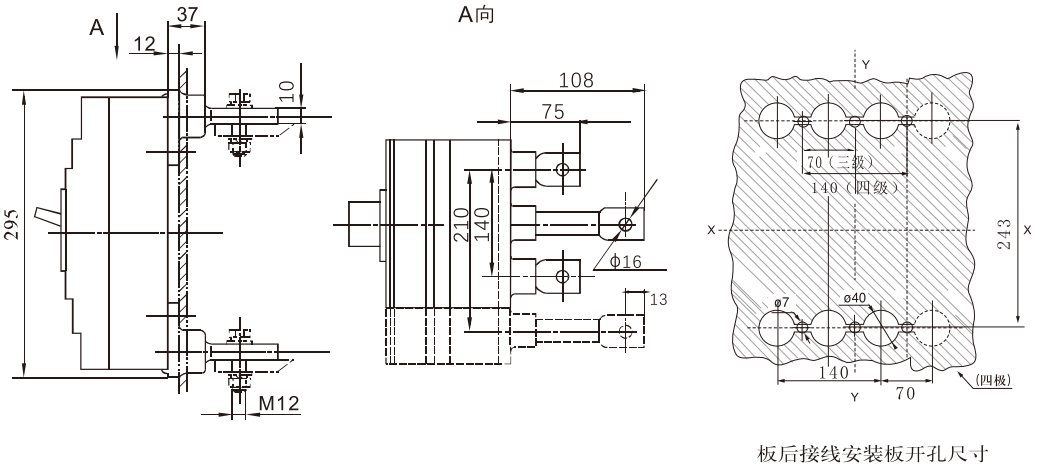
WHKM3E-630 board rear wiring (three-pole, four-pole) X-X, Y-Y are the center of three-pole circuit breaker
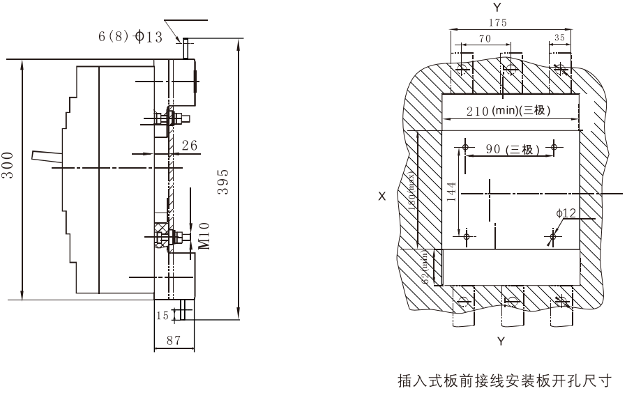
WHKM3E-630 plug-in board front wiring X-X, Y-Y are the center of three-pole circuit breaker
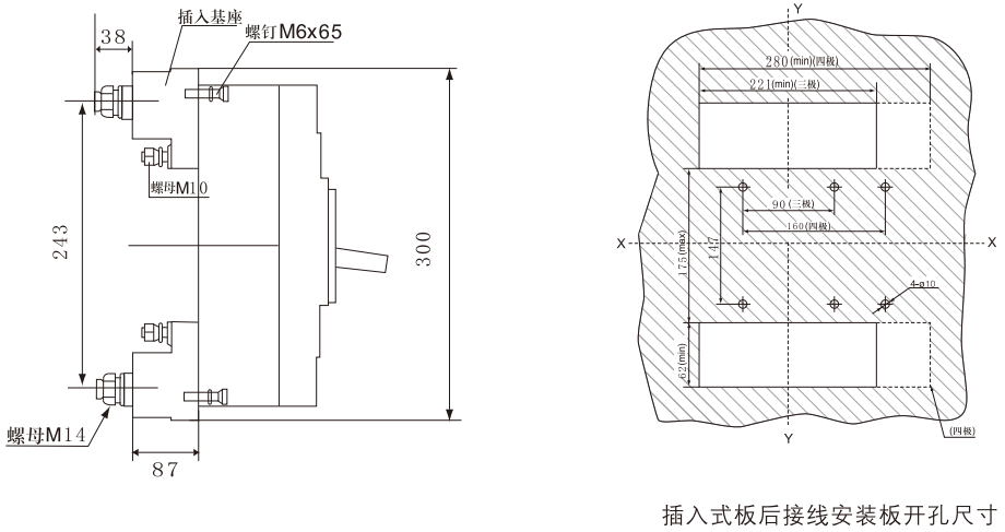
WHKM3E-630 Plug-in board rear wiring (three-pole, four-pole) X-X, Y-Y are the center of three-pole circuit breaker
WHKM3E-800 board front wiring (three-pole, four-pole) X-X, Y-Y are three-pole circuit breaker centers
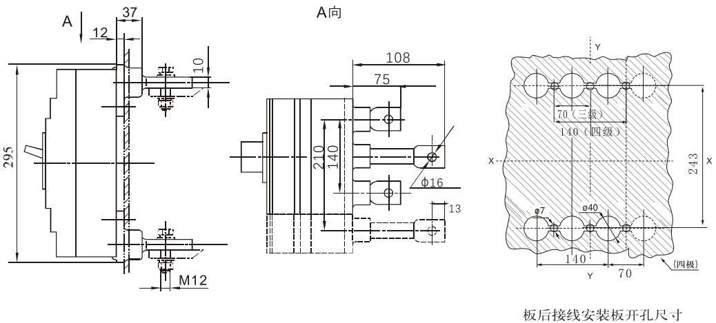
WHKM3E-800 board rear wiring (three-pole, four-pole) X-X, Y-Y are three-pole circuit breaker centers
WHKM3E-800 plug-in board front wiring X-X, Y-Y are three-pole circuit breaker center
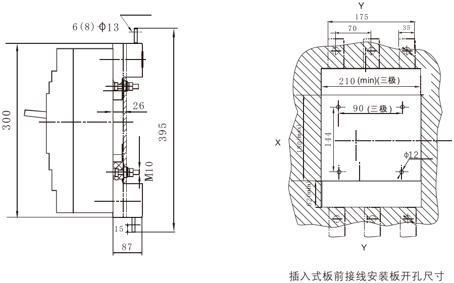
WHKM3E-800 plug-in board rear wiring (three-pole, four-pole) X-X, Y-Y are three-pole circuit breaker centers

Internal and External Accessories
Internal accessories of the circuit breaker (according to the user's needs, the circuit breaker accessories can be directly led out to wiring, or the lead out terminal block can be installed).
1. Under-voltage release device: 50HzAC230V, AC400V optional (Table 9)
| Equipped circuit breaker | Undervoltage Release Power (VA) | |
|---|---|---|
| AC230V | AC400V | |
| WHKM3E-125 | 2.6 | 3.3 |
| WHKM3E-250 | 3.8 | 3.3 |
| WHKM3E-400 | 3.7 | 2.7 |
| WHKM3E-630 | 2.3 | 2.7 |
| WHKM3E-B00 | 2.5 | 2.8 |
* Undervoltage release module thickness: 20mm
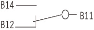
At 35% ~ 70% of the rated working voltage, the undervoltage release device should reliably trip the circuit breaker.
At 85%-110% of the rated working voltage, the undervoltage release should ensure that the circuit breaker can be closed;
When the rated operating voltage is less than 35%, the undervoltage release shall prevent the circuit breaker from closing.
Warning: The undervoltage release must be energized before the circuit breaker can be closed and closed again. Otherwise, the circuit breaker will be damaged!
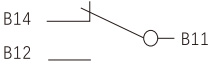
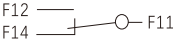
2. Shunt release
Wiring diagram (the internal accessories of the switch are in the virtual frame)
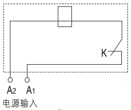
K: The micro switch connected in series with the coil inside the shunt release device is a normally closed contact. When the circuit breaker is opened, the contact opens itself and closes when it is closed.
Voltage specifications: AC50Hz, 230V or 400V; DC220V or 24V Note: DC24V is not recommended) When the rated control power supply voltage is between 70 and 110%, the shunt release should reliably trip the circuit breaker.
Dimensional drawing of shunt module installation
* Shunt release long wire type wire length: 50mm
Shunt release terminal type thickness: 20mm
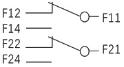
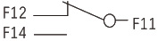
◆ Alarm contact
| Circuit breaker is in "on" and "closed" position |
|
| Position when the circuit breaker is "free trip" (alarm) |
|
※ Alarm contact long wire type wire length: 50mm
Alarm contact terminal type thickness: 20mm
◆ Auxiliary contact
| The circuit breaker is in the position when it is "divided" |
|
Circuit breaker with shell grade current 400A and above (one set is four pairs of contacts) |
|
Circuit breaker with shell grade current 250A and above (one set is two pairs of contacts) | |
| Circuit breaker in "closed" position |
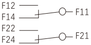
|
Circuit breaker with shell grade current 400A and above (one set is four pairs of contacts) |
|
Circuit breaker with shell grade current 250A and below (one set is two pairs of contacts) |
※ Auxiliary contact long wire type wire length: 50mm
Auxiliary contact terminal type thickness: 20mm
◆ Rated current of auxiliary contact and alarm contact
|
Shell frame grade Current rating inm (A) |
Agreed heating current (A) | Rated operating current le (A) | ||
|---|---|---|---|---|
| AC400V | DC220V | |||
| Auxiliary contact | ≤250 | 3 | 0.3 | 0.15 |
| ≥400 | 3 | 0.4 | 0.2 | |
| Alarm contact | ≤800 | 3 | 0.3 | 0.15 |
◆ Power-on operation performance of auxiliary contacts and corresponding test conditions
| Use categories | Turn on | Break off |
Power on and explode No. of cycles |
Operations per minute No. of cycles |
Power-on time | ||||
|---|---|---|---|---|---|---|---|---|---|
| I/Ie | U/Ue | COSφ or T0.95 | I/Ie | U/Ue | COSφ or T095 | ||||
| AC-15 | 10 | 1 | 0.3 | 1 | 1 | 03 | 6050 | 6 | ≥ 0. 05 s |
| DC-13 | 1 | 1 | 6Pe | 1 | 1 | 6Pe | ≥ T 0. 95 | ||
◆ On and off capability of auxiliary contact under abnormal condition
| Use categories | Turn on | Break off |
Power-on operation No. of cycles |
Operations per minute No. of cycles |
Power-on time | ||||
|---|---|---|---|---|---|---|---|---|---|
| I/Ie | U/Ue | COSφ or T0.95 | I/Ie | U/Ue | COSφ or T0.95 | ||||
| AC-15 | 10 | 1 | 03 | 10 | 1.1 | 03 | 10 | 2 | ≥ 0. 05 s |
| DC-13 | 1.1 | 1 | 6Pe | 1.1 | 1.1 | 6Pe | ≥ T 0. 95 | ||
Note: Table 2 above
1, 6 Pe = T0.95 is an empirical formula, where Pe is in "watts" and T0.95 is in milliseconds.
2. When the total number of operating performances of the circuit breaker is less than 6050 times, the number of energized operating performances of the auxiliary contact can be equal to the total number of operating performances of the circuit breaker.
3. The operating frequency and energization time allow an interaction with the main circuit of the circuit breaker.
◆ Electric operating mechanism wiring diagram
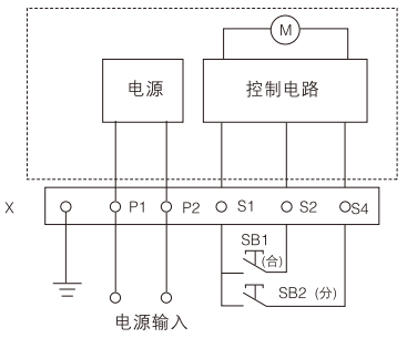
Symbol description:
SB1, SB2 operation buttons (user's own)
X Terminal Block
P1 and P2 are external power supplies. When the external power supply is DC 24V, P1 is connected to "+" and P2 is connected to "-".
(Inside the virtual frame is the internal wiring diagram of the electric operating mechanism)
◆ Starting Current, Power and Life of Electric Operating Mechanism
| Equipped circuit breaker | Starting Current (A) | Life (times) | ||||||
|---|---|---|---|---|---|---|---|---|
| Electromagnet type | Electric motor type | Electromagnet type | Electric motor type | Electromagnet type | Electric motor type | |||
| CD | CD2 | CD | CD2 | |||||
| WHKM3E-125 | ≤7 | ≤0.5 | 154 | 14 | 10000 | 10000 | ||
| WHKM3E-250 | ≤8.5 | ≤0.5 | 187 | 14 | 8000 | 8000 | ||
| WHKM3E-400 | - | ≤5.7 | ≤2 | - | 120 | - | 5000 | |
| WHKM3E-630 | - | ≤5.7 | ≤2 | - | 120 | - | 5000 | |
| WHKM3E-800 | - | ≤5.7 | ≤2 | - | 120 | - | 3000 | |
◆ Height of electric operating mechanism
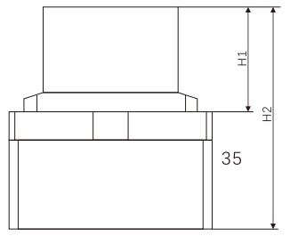
◆ Total height of circuit breaker after installation of electric operating mechanism
| Model of circuit breaker equipped with operating mechanism | WHKM3E-125 | WHKM3E-250 | WHKM3E-400 | WHKM3E-630 | WHKM3E-800 | |
|---|---|---|---|---|---|---|
| Height (mm) | H1 | 93.5 | 95 | 151 | 152 | 152 |
| H2 | 175.5 | 180 | 249.7 | 255 | 255 | |