Search for what you are looking for
Distribution electrical appliances
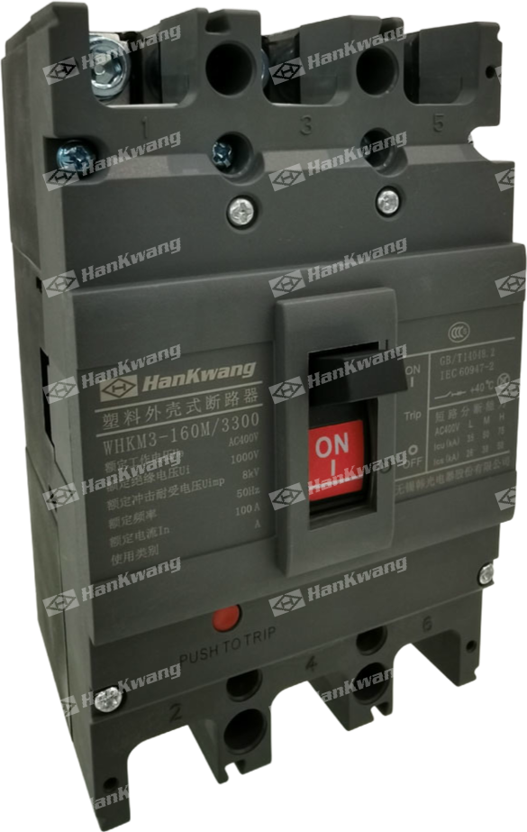
WHKM3 MCCB
The WHKM3 series molded case circuit breaker (hereinafter referred to as the circuit breaker) is a new type of circuit breaker developed by our company using advanced iional design and manufacturing technology. With a rated insulation voltage of 1000V, it is suitable for circuits with an AC frequency of 50Hz, a rated operag voltage of 690V or less, and a rated operating current up to 800A, for infrequent switching and infrequent motor starting. The circuit breaker featues overload, short-circuit, and undervoltage protection functions, capable of protecting circuits and power supply equipment from damage.
Product Details
Model and Meaning
Technical Specifications
Appearance and dimensions
Other
The WHKM3 series molded case circuit breakers (hereinafter referred to as circuit breakers) are a new type of circuit breaker developed by our cing advanced international design and manufacturing technologies. With a rated insulation voltage of 1000V, they are suitable for circuits with an AC frequency of 5ed operating voltage of 690V or less, and a rated operating current up to 800A, for infrequent switching and infrequent motor starting. The cuit breakers feature overload, short-circuit, and undervoltage protection functions, safeguarding circuits and power equipment from damage. Classified according to their rated ultimate short-circuit breakingapacity (Icu), the circuit breakers are divided into three types: L-type (standard type), M-type (higher breaking type), and H-type (high breaking type). Characterizecompact size, high breaking capacity, short arc distance, and vibration resistance, these circuit breakers are ideal for use on land and ships.
The circuit breaker can be installed vertically (i.e. vertically) or horizontally (i.e. horizontally).
This circuit breaker cannot be poured into wires, that is, only 1, 3 and 5 can be connected to power lines, and 2, 4 and 6 can be connected to load lines.
This circuit breaker has isolation function.
| WHK | M | 3 | — | ☐ | ☐ | ☐ | / | ☐ | ☐ | ☐ |
|---|---|---|---|---|---|---|---|---|---|---|
| Enterprise code |
Plastic housing Type circuit breaker |
Design serial number |
Shell frame grade Rated current |
Rated limit Short circuit break Competency Level |
Mode of operation (2 |
Number of poles |
Tripping method and Attachment code (See Table 2) |
Use Code (1 |
Note: 1) Circuit breakers for distribution have no code; Circuit breakers for protecting motors are denoted by 2.
2) Direct operation without code; Electric operation is denoted by P; Turning the handle operation is indicated by Z.
| Model |
Cabinet rating Rated current (A) |
Rated current (A) |
Rated insulation voltage (V) |
Rated impulse withstand voltage (kV) |
Rated short-circuit breaking capacity kA 400V |
Rated short-circuit breaking capacity kA 690V |
Rated short-circuit breaking capacity for operation kA 400V |
Rated short-circuit breaking capacity for operation kA 690V |
Service life (times) |
Dimensions of the shape |
Installation dimensions (In front of the board) |
|||||
|---|---|---|---|---|---|---|---|---|---|---|---|---|---|---|---|---|
| Electrical | Mechanical | L |
W 3P/4P |
H | A | B | 4-qd | |||||||||
| WHKM3-63L | 63 |
10、16、20、25 32、40、50、63 |
1000 | 8 | 28 | - | 20 | - | 7000 | 10000 | 142 | 78 | 73.5 | 25 | 17 | φ3.5 |
| WHKM3-63M | 50 | - | 38 | - | 7000 | 10000 | 42 | 78/103 | 81.5 | |||||||
| WHKM3-100L | 100 |
10、16、20、 25、32、40、50、 63、80、100 |
1000 | 8 | 35 | - | 26 | - | 7000 | 10000 | 157 | 92 | 69 | 30 | 29 | φ4.5 |
| WHKM3-100M | 50 | 20 | 38 | 10 | 7000 | 10000 | 157 | 92/122 | 87 | |||||||
| WHKM3-100H | 75 | 20 | 50 | 10 | 7000 | 10000 | ||||||||||
| WHKM3-160L | 160 |
100、125 140、160 |
1000 | 8 | 35 | - | 26 | - | 7000 | 10000 | 157 | 92 | 69 | 30 | 29 | φ4.5 |
| WHKM3-160M | 50 | 20 | 38 | 10 | 7000 | 10000 | 157 | 92/122 | 87 | |||||||
| WHKM3-160H | 75 | 20 | 50 | 10 | 7000 | 10000 | ||||||||||
| WHKM3-250L | 250 |
100、125 140、160 180、200 225、250 |
1000 | 8 | 35 | - | 26 | - | 7000 | 10000 | 165 | 107 | 88 | 35 | 26 | φ4.5 |
| WHKM3-250M | 50 | 20 | 38 | 10 | 7000 | 10000 | 165 | 107/142 | 105 | |||||||
| WHKM3-250H | 75 | 20 | 50 | 10 | 7000 | 10000 | ||||||||||
| WHKM3-400L | 400 |
225、250、315、 350、400 |
1000 | 12 | 50 | - | 38 | - | 7000 | 10000 | 257 | 150/198 | 110 | 44 | 94 | φ7 |
| WHKM3-400M | 65 | 20 | 49 | 10 | 7000 | 10000 | 257 | 150/198 | 110 | |||||||
| WHKM3-400H | 85 | 20 | 65 | 10 | 7000 | 10000 | ||||||||||
| WHKM3-630L | 630 | 400、500、630 | 1000 | 12 | 65 | - | 42 | - | 7000 | 10000 | 270 | 82/240 | 110 | 58 | 200 | φ7 |
| WHKM3-630M | 75 | 20 | 50 | 15 | 7000 | 10000 | 270 | 182/240 | 110 | |||||||
| WHKM3-630H | 85 | 20 | 65 | 15 | 7000 | 10000 | ||||||||||
| WHKM3-800M | 800 | 630、700、800 | 1000 | 12 | 75 | 20 | 56 | 15 | 7000 | 10000 | 280 | 210/280 | 115.5 | 70 | 243 | φ7 |
| WHKM3-B00H | 85 | 20 | 65 | 15 | 7000 | 10000 | ||||||||||
This circuit breaker meets the following standards:
IEC60947-2 and GB 14048.2 Low voltage circuit breaker
IEC60947-4 and GB14048.4 Contactors and motor starters
IEC60947-5. 1 and GB14048.5 Electromechanical control circuit electrical appliances
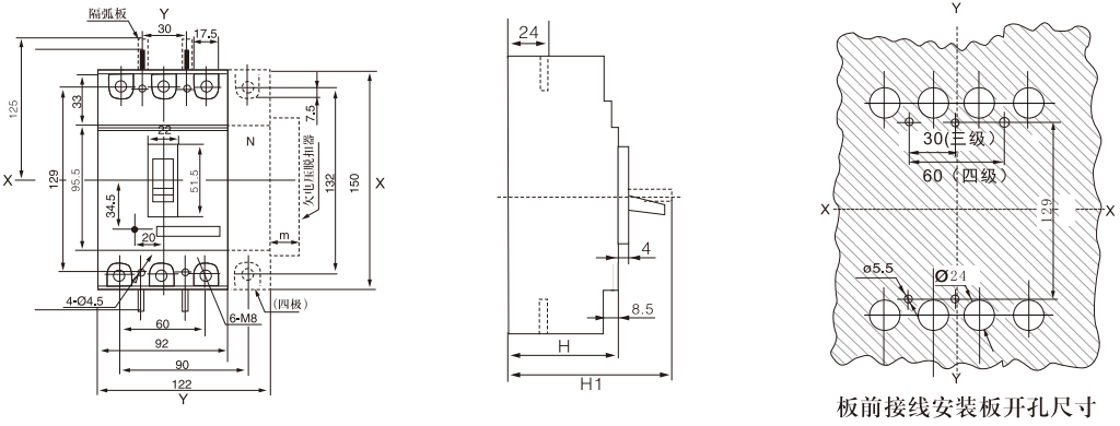
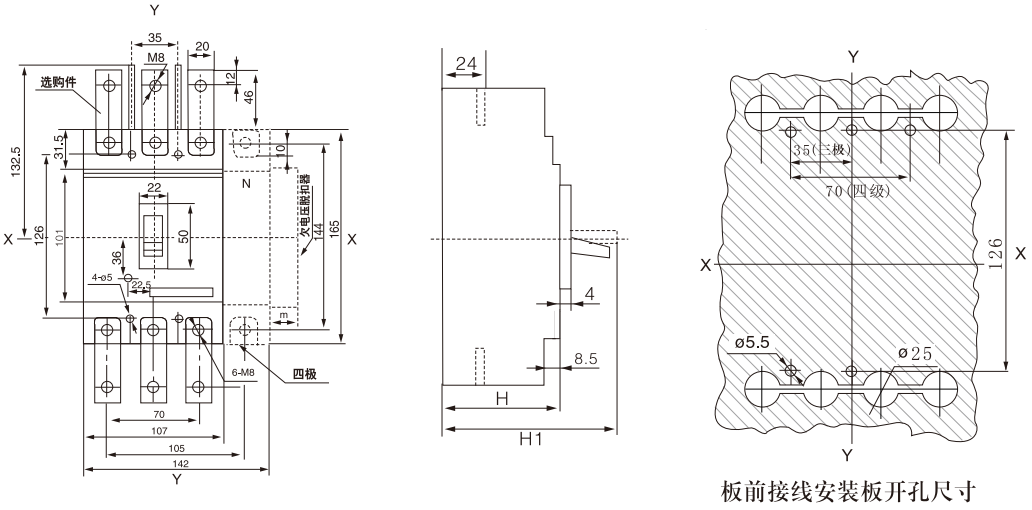
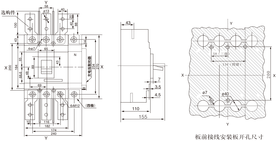
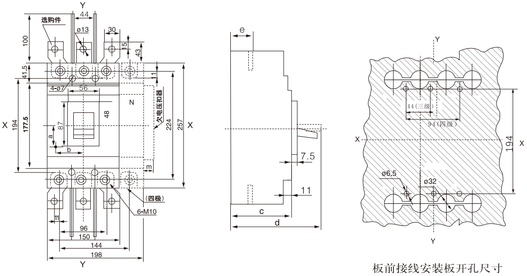
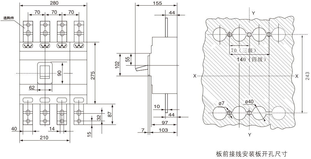
WHKM3-63 (L, M) board front wiring size (three-pole, four-pole) X-X, Y-Y three-pole circuit breaker center
| Model | H | H1 | H2 |
|---|---|---|---|
| WHKM3-63L | 73.5 | 90.5 | 20.5 |
| WHKM3-63M | 81.5 | 98.5 | 28.5 |
| WHKM3-63 quadrupole | 81.5 | 98.5 | 28.5 |
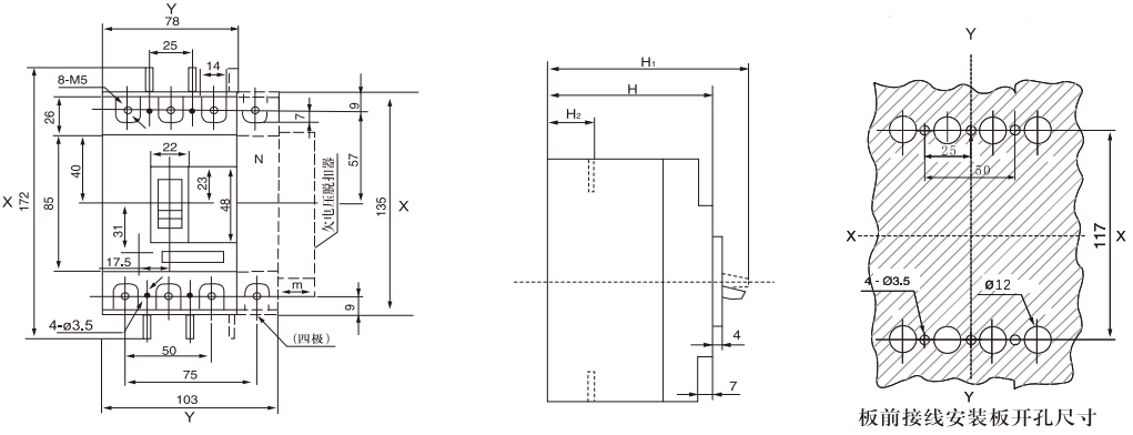
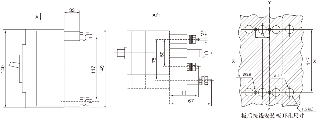
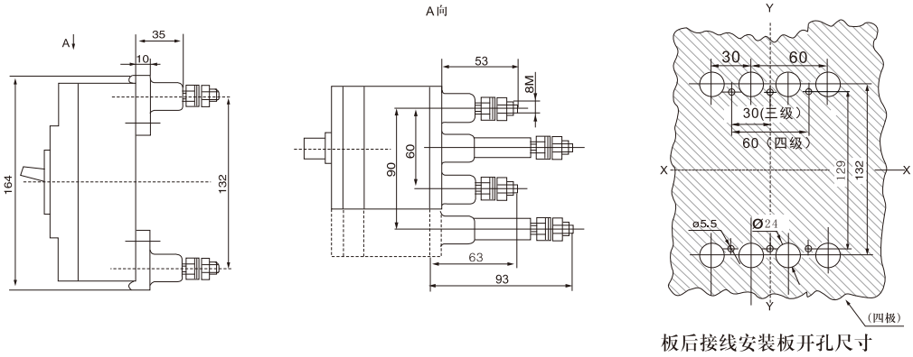
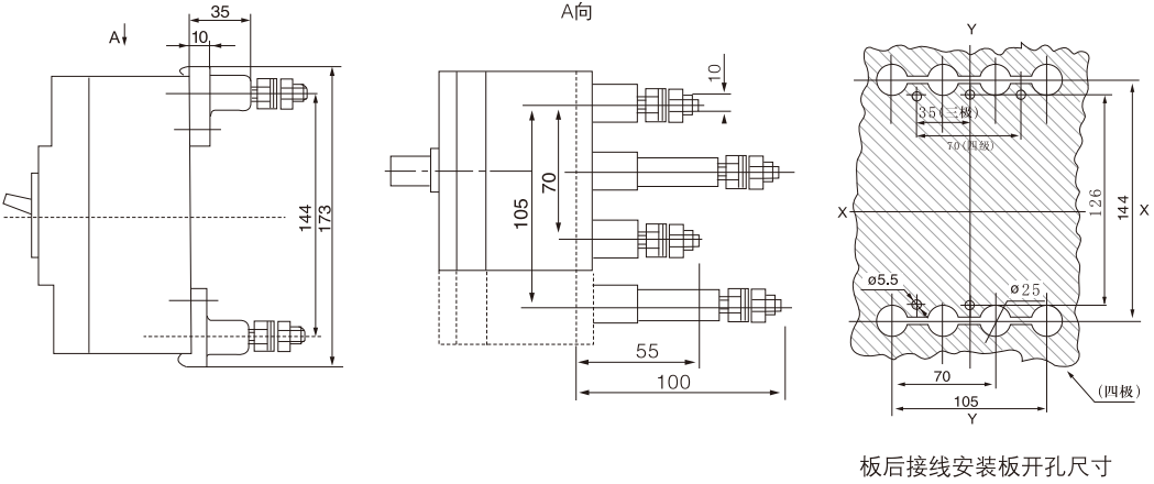
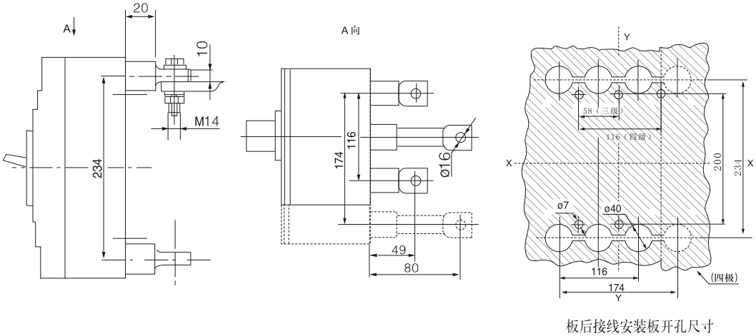
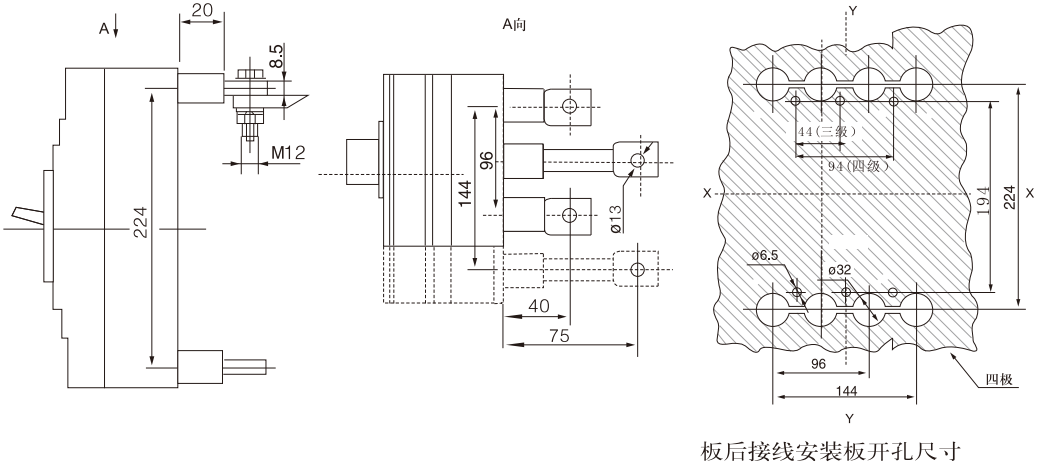
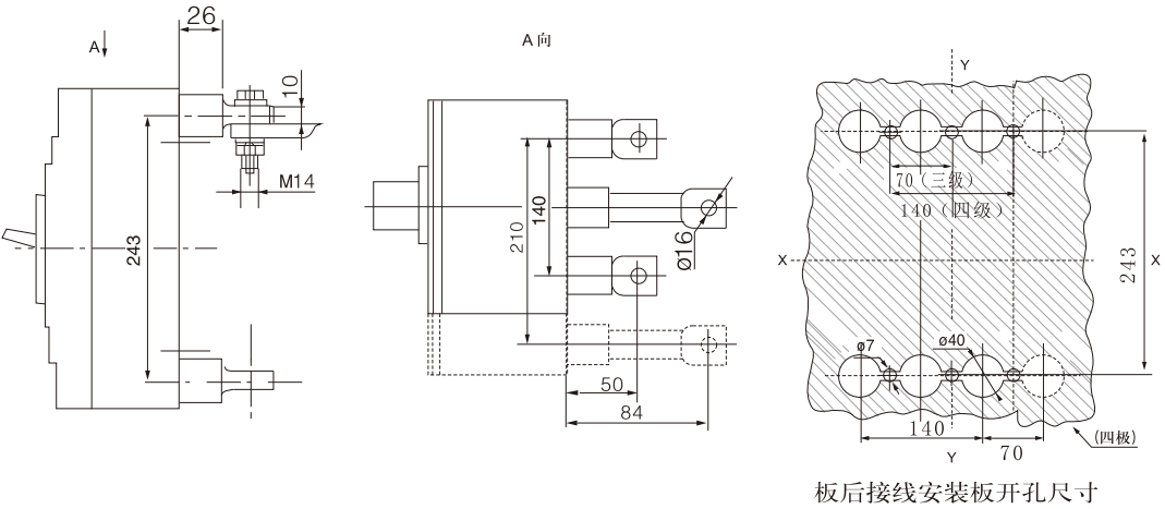
WHKM3-63 (L, M) board rear wiring dimensions (three-pole, four-pole) X-X, Y-Y three-pole circuit breaker center
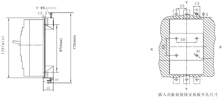
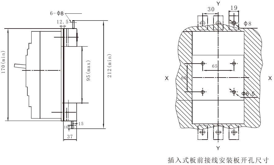
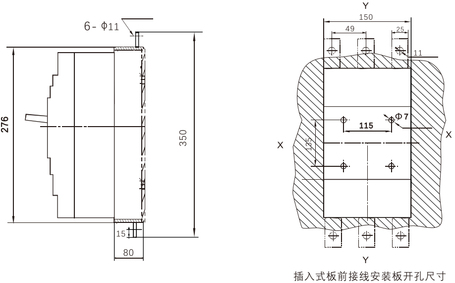
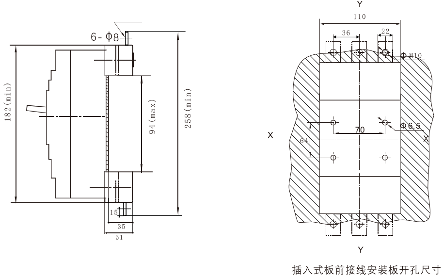
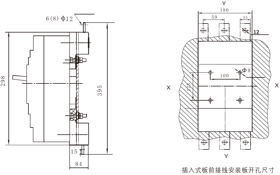
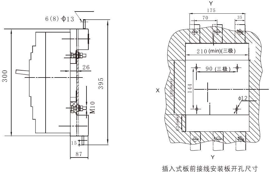
WHKM3-63 (L, M) plug-in board front wiring size (three poles) X-X, Y-Y are the center of three pole circuit breaker
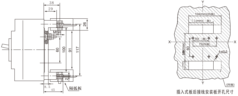
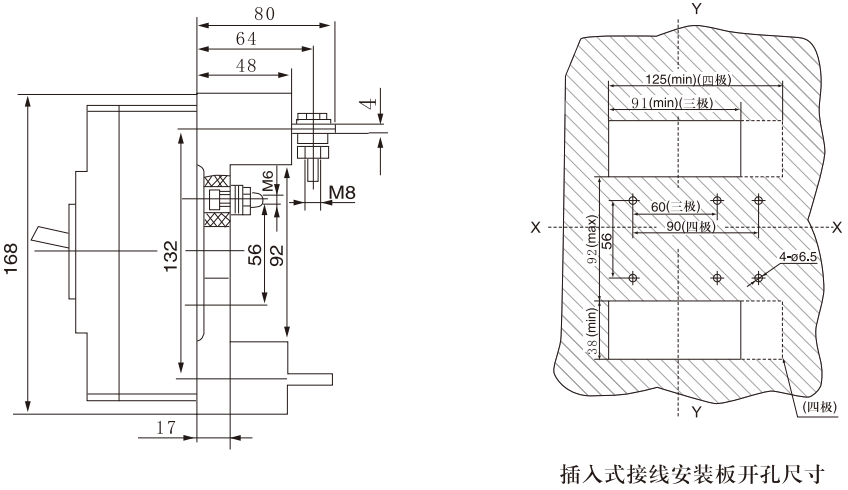
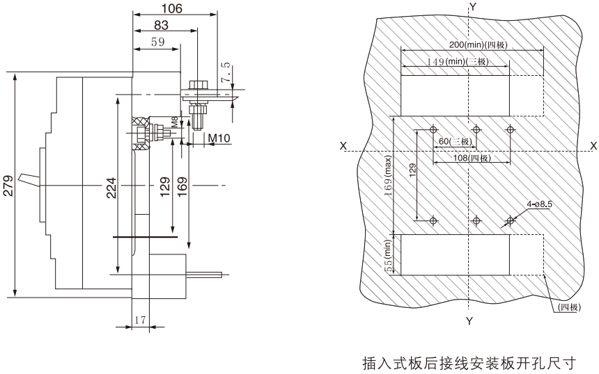
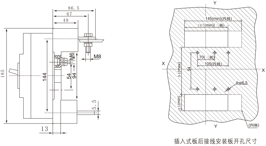
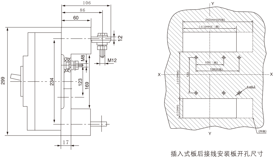
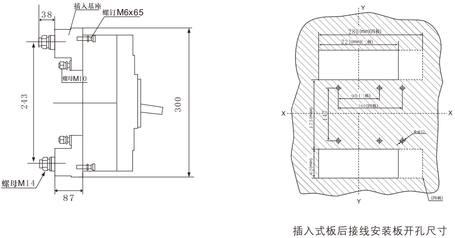
WHKM3-63 (L, M) Plug-in Board Rear Wiring Dimensions (3-pole, 4-pole) X-X, Y-Y 3-pole circuit breaker center
WHKM3-100, WHKM3-160 (L, M, H) board front wiring dimensions (three-pole, four-pole) X-X, Y-Y three-pole circuit breaker center
| Model | H | H1 |
|---|---|---|
| WHKM3-100/160L | 69 | 86 |
| WHKM3-100/160M, WHKM3-100/160H | 87 | 104 |
WHKM3-100, WHKM3-160 (L, M, H) board rear wiring dimensions (three-pole, four-pole) X-X, Y-Y three-pole circuit breaker center
WHKM3-100, WHKM3-160 (L, M, H) plug-in board front wiring size (three poles) X-X, Y-Y are the center of three pole circuit breaker
WHKM3-100, WHKM3-160 (L, M, H) rear wiring size of plug-in board (three-pole, four-pole) X-X, Y-Y are the center of three-pole circuit breaker
WHKM3-250 (L, M, H) board front wiring dimensions (three-pole, four-pole) X-X, Y-Y are three-pole circuit breaker center
| Model | H | H1 |
|---|---|---|
| WHKM3-250L | 88 | 110 |
| WHKM3-250M, WHKM3-250H | 105 | 127 |
WHKM3-250 (L, M, H) rear wiring dimensions (three-pole, four-pole) X-X, Y-Y are the center of three-pole circuit breaker
WHKM3-400 (L, M, H) plug-in board front wiring size (three poles) X-X, Y-Y are the center of three pole circuit breaker
WHKM3-400 (L, M, H) plug-in board rear wiring dimensions (three-pole, four-pole) X-X, Y-Y are the center of three-pole circuit breaker
WHKM3-630 (L, M, H) board front wiring dimensions (three-pole, four-pole) X-X, Y-Y are the center of three-pole circuit breaker
WHKM3-630 (L, M, H) rear wiring dimensions (three-pole, four-pole) X-X, Y-Y are the center of three-pole circuit breaker
WHKM3-250 (L, M, H) plug-in board front wiring dimensions (three poles) X-X, Y-Y are three pole circuit breaker centers
WHKM3-250 (L, M, H) plug-in board rear wiring dimensions (three-pole, four-pole) X-X, Y-Y are the center of three-pole circuit breaker
WHKM3-400 (L, M, H) board front wiring dimensions (three-pole, four-pole) X-X, Y-Y are the center of three-pole circuit breaker
| Model | a | b | c | d | e |
|---|---|---|---|---|---|
| WHKM3-400 | 43 | 57 | 110 | 150 | 39 |
WHKM3-400 (L, M, H) rear wiring dimensions (three-pole, four-pole) X-X, Y-Y are the center of three-pole circuit breaker
WHKM3-630L, M, H) Plug-in board front wiring dimensions (three poles) X-X, Y-Y are three pole circuit breaker centers
WHKM3-630 (L, M, H) Plug-in board rear wiring dimensions (three-pole, four-pole) X-X, Y-Y are the center of three-pole circuit breaker
WHKM3-800 (M, H) board front wiring dimensions (three-pole, four-pole) X-X, Y-Y are the center of three-pole circuit breaker
WHKM3-800 (M, H) board rear wiring dimensions (three-pole, four-pole) X-X, Y-Y are the center of three-pole circuit breaker
WHKM3-800 (M, H) plug-in board front line dimensions (three poles) X-X, Y-Y are three-pole circuit breaker centers
WHKM3-800 (M, H) plug-in board rear wiring dimensions (three-pole, four-pole)
Internal and External Accessories
Internal accessories of the circuit breaker (according to the user's needs, the circuit breaker accessories can be directly led out to wiring, or the lead out terminal block can be installed).
1. Under-voltage release: 50Hz AC230V, AC400V optional
Undervoltage release power (Table IX)
| Equipped circuit breaker | Undervoltage Release Power (VA) | |
|---|---|---|
| AC230V | AC400V | |
| WHKM3-63 | 3.5 | 3.3 |
| WHKM3-100 | 2.6 | 3.3 |
| WHKM3-160 | 2.6 | 3.3 |
| WHKM3-250 | 3.8 | 3.3 |
| WHKM3-400 | 3.7 | 2.7 |
| WHKM3-630 | 2.3 | 2.7 |
| WHKM3-800 | 2.5 | 2.8 |
At 35% ~ 70% of the rated working voltage, the undervoltage release device should reliably trip the circuit breaker.
At 85%-110% of the rated working voltage, the undervoltage release should ensure that the circuit breaker can be closed;
When the rated operating voltage is less than 35%, the undervoltage release shall prevent the circuit breaker from closing.
Warning: The undervoltage release must be energized before the circuit breaker can be closed and closed again. Otherwise, the circuit breaker will be damaged!
※ (Under-voltage release thickness: 20 mm)
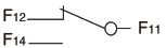
2. Shunt release
Wiring diagram (the internal accessories of the switch are in the dummy frame)
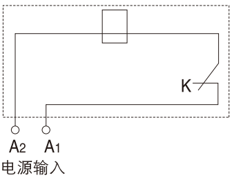
K: The micro switch connected in series with the coil inside the shunt release device is a normally closed contact. When the circuit breaker is opened, the contact opens itself and closes when it is closed.
Voltage specifications: AC50Hz, 230V or 400V; DC220V or 24V (Note: DC24V is not recommended)
Between 70 and 110% of the rated control power supply voltage, the shunt release shall reliably trip the circuit breaker.
※ (Shunt release long wire type wire length: 50mm)
(Shunt Release Terminal Type Thickness: 20 mm)
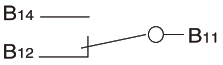
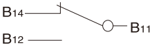
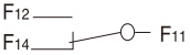
3. Alarm contacts
| Circuit breaker is in "on" and "closed" position |
|
| Position when the circuit breaker is "free trip" (alarm) |
|
※ (Alarm contact long wire type wire length: 50mm) (Alarm contact terminal type thickness: 20mm)
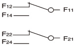
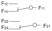
4. Auxiliary contacts
| The circuit breaker is in the position when it is "divided" |
|
Circuit breaker with shell grade current 400A and above (one set is four pairs of contacts) |
|
Circuit breaker with shell grade current 250A and below (one set is two pairs of contacts) | |
| Position when the circuit breaker is "closed" |
|
Circuit breaker with shell grade current 400A and above (one set is four pairs of contacts) |
|
Circuit breaker with shell grade current 250A and below (one set is two pairs of contacts) |
※ (Auxiliary contact long wire type wire length: 50mm) Auxiliary contact terminal type thickness: 20mm)
4.1 Rated current of auxiliary contacts and alarm contacts (Table 10)
| Current rating of shell and frame grade lnm (A) | Agreed heating current ln (A) | Rated operating current le (A) | ||
|---|---|---|---|---|
| AC400V | DC220V | |||
| Auxiliary contact | ≤250 | 3 | 0.3 | 0.15 |
| ≥400 | 3 | 0.4 | 0.2 | |
| Alarm contact | ≤800 | 3 | 0.3 | 0.15 |
4.2 Power-on operation performance of auxiliary contacts and corresponding test conditions (Table 11)
| Use categories | Turn on | Break off |
Power-on operation No. of cycles |
Fuck every minute Number of cycles |
Power-on time | ||||
|---|---|---|---|---|---|---|---|---|---|
| I/le | U/Ue | Cos φ or T0.95 | I/le | U/Ue | Cos φ or T0.95 | ||||
| AC-15 | 10 | 1 | 0.3 | 1 | 1 | 0.3 | 6050 | 6 | ≥ 0. 05 s |
| DC-13 | 1 | 1 | 6Pe | 1 | 1 | 6Pe | ≥ To.95 | ||
4.3 Switching on and breaking capacity of auxiliary contacts under abnormal conditions (Table 12)
| Use categories | Turn on | Break off |
Power-on operation No. of cycles |
Operations per minute No. of cycles |
Power-on time | ||||
|---|---|---|---|---|---|---|---|---|---|
| I/le | U/Ue | COsφ or T0.95 | I/le | U/Ue | Cos φ or To.95 | ||||
| AC-15 | 10 | 1.1 | 0.3 | 10 | 1.1 | 0.3 | 10 | 2 | ≥0.058 |
| DC-13 | 1.1 | 1.1 | 6Pe | 1.1 | 1.1 | 6Pe | ≥ T 0. 95 | ||
Note: Table 2 above
1.6 Pe = T0.95 is the empirical formula, where Pe is in "watts" and T0.95 is in milliseconds.
2. When the total number of operating performances of the circuit breaker is less than 6050, the number of energized operating performances of the auxiliary contact may be equal to the total number of operating performances of the circuit breaker.
3. The operating frequency and energization time are allowed to be consistent with those of the main circuit of the circuit breaker.
2. External accessories for circuit breakers
2.1 Mechanical interlocking mechanism of two circuit breakers
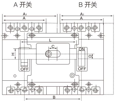
Table 13
| Product Name | A | A1 | B | C | D | L | H | Note |
|---|---|---|---|---|---|---|---|---|
| WHKM3-63 | 78 | 102 | 18 | 13 | 95 | 22 | For use in WHKM3-63L、M、 | |
| WHKM3-100/160 | 92 | 120 | 18 | 11.5 | 118 | 22 | For use in WHKM3-100/160L、M、H | |
| WHKM3-250 | 107 | 135 | 18 | 9 | 130 | 22 | For use in WHKM3-250L、M、H | |
| WHKM3-400 | 150 | 190 | 42 | 16 | 175 | 22 | For use in WHKM3-400L、M、H | |
| WHKM3-630 | 182 | 220 | 42 | 12 | 198 | 22 | For use in WHKM3-630L、M、H | |
| WHKM3-800 | 210 | 240 | 42 | 29.5 | 230 | 20 | For use in WHKM3-800 M、H | |
| WHKM3-63/4P | 103 | 132 | 18 | 13 | 125 | 22 | For use in WHKM3-63 Quadrant | |
| WHKM3-100/160/4P | 122 | 152 | 18 | 11.5 | 150 | 22 | For use in WHKM3-100/160 Quadrant | |
| WHKM3-250/4P | 142 | 173 | 18 | 9 | 168 | 22 | For use in WHKM3-250 Quadrant | |
| WHKM3-400/4P | 198 | 240 | 42 | 16 | 225 | 22 | For use in WHKM3-400 Quadrant | |
| WHKM3-630/4P | 240 | 280 | 42 | 12 | 258 | 22 | For use in WHKM3-630 Quadrant | |
| WHKM3-800/4P | 280 | 310 | 46 | 22 | 300 | 20 | For use in WHKM3-800 Quadrant |
2.2 Electric operating mechanism
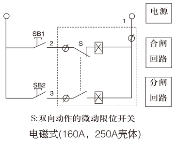
Schematic diagram of electromagnet operation opening and closing (the external accessories of the switch are inside the virtual frame)
Motor operation opening and closing circuit diagram (the external accessories of the switch are in the virtual frame)
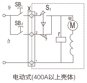
Symbol description:
SB1, SB2 operation buttons (provided by the user)
x terminal block
S3 Micro Switch
M special series motor
r brake electromagnet
Specification: AC AC50Hz230V or 400V
2.2. 1 Starting current, power and life of motor operating mechanism (Table 14)
| Equipped circuit breaker | Starting electricity | Stream (A) | Starting Power (VA) | Life (times) | ||||
|---|---|---|---|---|---|---|---|---|
| Electromagnet type | Electric motor type | Electromagnet type | Electric motor type | Electromagnet type | Electric motor type | |||
| CD | CD2 | CD | CD2 | |||||
| WHKM3-63L, M | ≤5 | ≤0.5 | 110 | 14 | 10000 | 10000 | ||
| WHKM3-100/160L, M, H | ≤7 | ≤0.5 | 154 | 14 | 10000 | 10000 | ||
| WHKM3-250L, M, H | ≤8.5 | ≤0.5 | 187 | 14 | 8000 | 8000 | ||
| WHKM3-400L, M, H | one | ≤5.7 | ≤2 | one | 120 | one | 5000 | |
| WHKM3-630L, M, H | one | ≤5.7 | ≤2 | one | 120 | one | 5000 | |
| WHKM3-800M, H | one | ≤7.5 | ≤2 | one | 120 | one | 3000 | |
2.2. 2 Height of electric operating mechanism
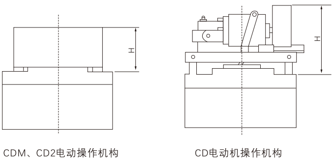
2.2. 3 Total height of circuit breaker after installation of electric operating mechanism (Table 15)
| Model of circuit breaker equipped with operating mechanism |
WHKM3-63 L, M |
WHKM3-100/160 L, M, H |
WHKM3-250 L, M, H |
WHKM3-400 L, M, H |
WHKM3-630 L, M, H |
WHKM3-800 M, H |
|
|---|---|---|---|---|---|---|---|
| Height H (mm) | Electromagnet type | 91 | 91 | 101 | |||
| Electric motor type | 88.5 | 89.5 | 93 | 141 | 141 | 135 | |
※ Note: After the circuit breaker is tripped, the electric operating mechanism must first buckle the circuit breaker before it can be closed.
2.3 Turn handle operating mechanism
2.3. 1 Feature:
The operating mechanism adopts unique design and transmission structure, and realizes the breaking, closing and re-buckle of the molded case circuit breaker by rotating the handle. The operation is flexible and stable, the operation force is small, the installation is easy, and there is no need to adjust. The overall performance and quality of the mechanism are superior to other similar products. At the same time, the mechanism is equipped with a rotary handle. In order to meet the requirements of different users, our company can provide CS1 series, CS2 series and CZ series operating mechanisms for users to choose (universal for three-pole products and four-pole products).
2.3. 2 Use:
This organization specializes in For use in WHKM3 series molded case circuit breakers, which are operated on the panel by rotating the handle of solid glazed drawer chest, power distribution cabinet, power box, etc., and ensures that the cabinet door panel cannot be opened when the circuit breaker is closed (i.e. interlocked with the door).