Search for what you are looking for
Transfer switching equipment
Product Details
| Product Specifications | DCU8-W2 | DCU8-W3 | DCU9-W2 | DCU-A | DCU-B | DCU-HA | DCU-HB |
|---|---|---|---|---|---|---|---|
| Dimensions and Installation Method |
Snap-on or screw-fixed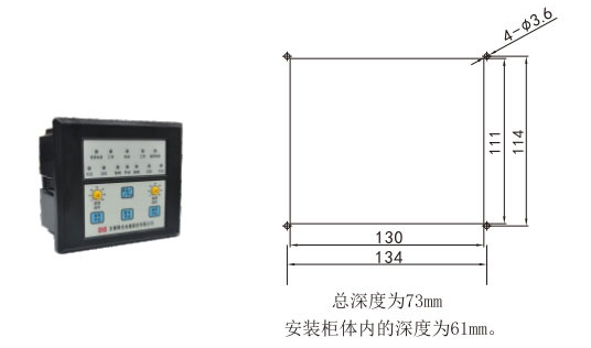
|
Snap-on type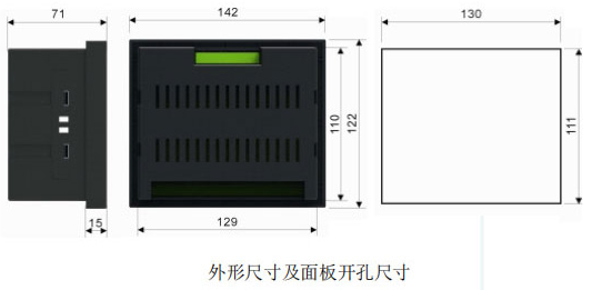
|
|||||
| Power indicator | ▲ | ▲ | ▲ | ▲ | ▲ | ▲ | ▲ |
| Closing signal | ▲ | ▲ | ▲ | ▲ | ▲ | ▲ | ▲ |
| Adjustable delay | ▲ | ▲ | ▲ | ▲ | ▲ | ▲ | ▲ |
| Manual/automatic adjustable | ▲ | ▲ | ▲ | ▲ | ▲ | ▲ | ▲ |
| Primary and backup power sources are prioritized. | ▲ | ▲ | ▲ | ▲ | ▲ | ▲ | ▲ |
| Self-initiated and self-replied / Self-initiated but not self-replied adjustable | ▲ | ▲ | ▲ | ▲ | ▲ | ▲ | ▲ |
| Power failure detection | ▲ | ▲ | ▲ | ▲ | ▲ | ▲ | ▲ |
| Under-voltage detection(≤187V±2V) | ▲ | ▲ | ▲ | ▲ | ▲ | Adjustable | Adjustable |
| Overvoltage detection(≥264V±2V) | ▲ | ▲ | ▲ | ▲ | ▲ | Adjustable | Adjustable |
| Phase loss detection | ▲ | ▲ | ▲ | ▲ | ▲ | ▲ | ▲ |
| Generator function | ▲ | ▲ | ▲ | ▲ | ▲ | ▲ | |
| Fire zero cut | ▲ | ▲ | |||||
| Power failure output | ▲ | ▲ | |||||
| Fault Record |
|
▲ | ▲ | ||||
| Liquid crystal |
|
▲ | ▲ | ||||
| RS485 Communication |
|
▲ | ▲ | ||||
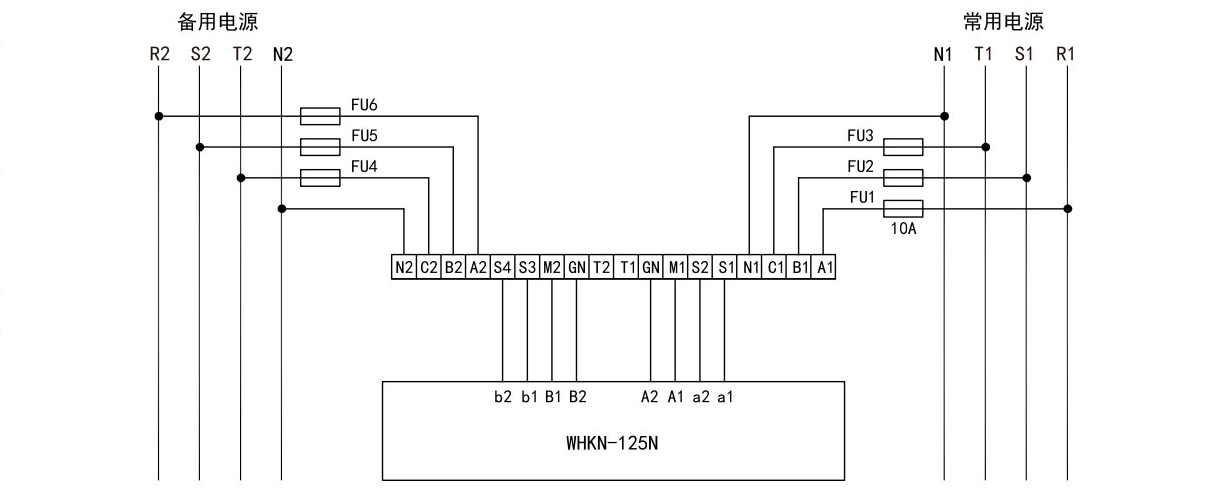
DCU series controller terminal block diagram
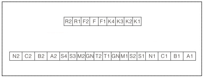
Terminal Description:
K1, K2: Common power supply failure output, normally open contact, the contact is closed when common power supply fails, and the contact is open when normal;
K3, K4: standby power failure output, normally open contact, the contact is closed when the standby power fails, and the contact is open when it is normal;
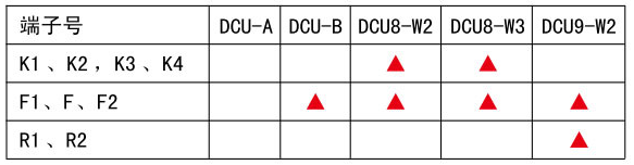
F1, F, F2: generator start and shut down signals, F is the common point, F1 is the normally open point, and the main power supply is closed when it is normal; F2 is the normally closed point. When the main power supply is abnormal, it will close with a delay of about 3s;
R1, R2: fire control input. When the fire control center provides a passive signal, short-circuit the R1R2 contact on the controller, which can force the switch to switch to the double-division position and cut off the load; When the fire signal is cancelled, the switch automatically switches;
Refer to the controller and switch wiring diagram for the remaining terminals.
DCU-HA Controller Block Diagram
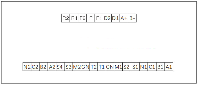
Terminal Description:
A +, B-: RS485 communication interface;
D1, D2: switch trip input;
F1, F, F2: generator start and shut-off signals, F is the common point, F1 is the normally open point, F2 is the normally closed point, F, F2 are closed when the main power supply is abnormal;
R1 and R2: fire control input. When the fire control center provides a passive signal, short-circuit the R1 and R2 contacts on the controller to force the switch to switch to the double-divided position and cut off the load.
DCU-HB Controller Block Diagram
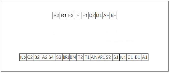
Terminal Description:
A +, B-: RS485 communication interface;
D1, D2: switch trip input;
F1, F, F2: generator start and shut-off signals, F is the common point, F1 is the normally open point, F2 is the normally closed point, F, F2 are closed when the main power supply is abnormal;
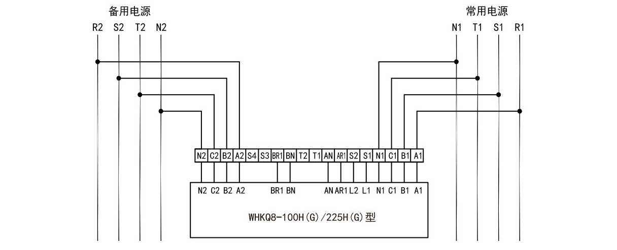
DCU8-W2、DCU-HB
WHKQ8-100H(G)、WHKQ8-225H(G)
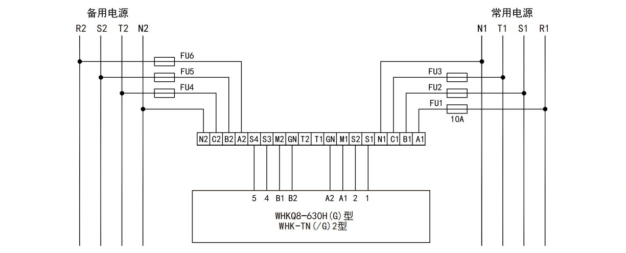
DCU8-W3、DCU-HA
WHKQ8-630H(G)、WHK-TN(/G)2
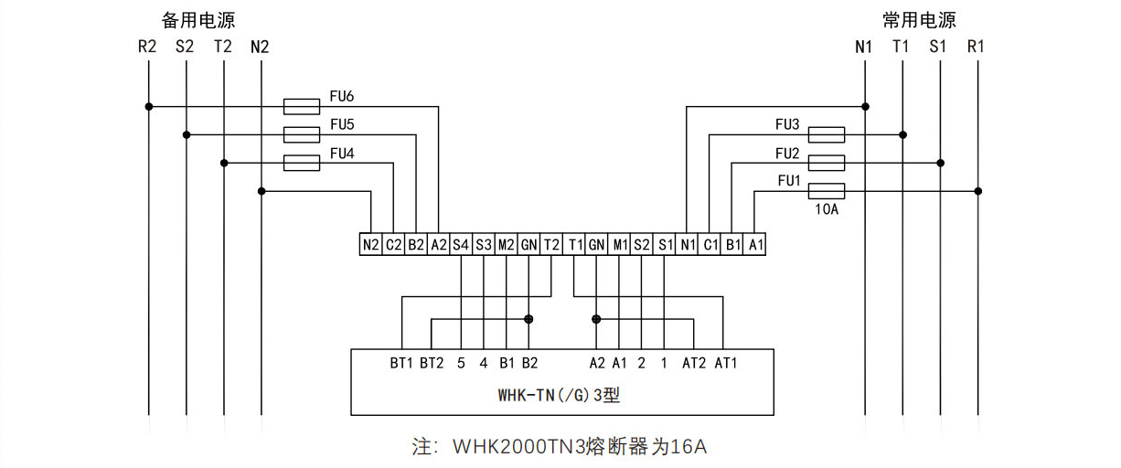
DCU9-W2、DCU-HA
WHK-TN(/G)3
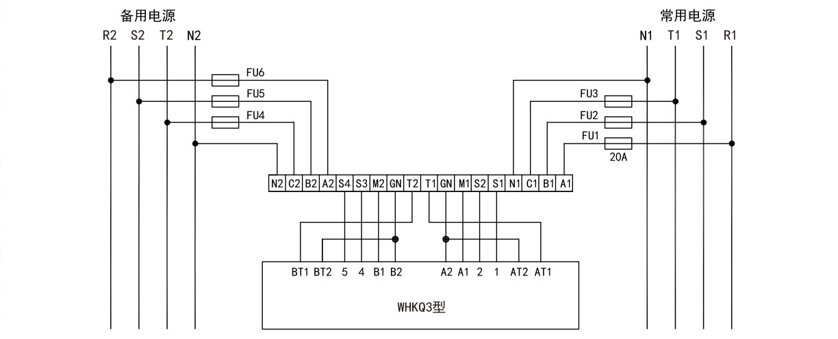
DCU9-W2
WHKQ3
DCU-A、DCU-B、DCU-HA
WHKN-125N